Manufacturer of high precision screw-cutting lathe 1E61MT Ulyanovsk Machine-Building Plant im. Volodarsky a diversified enterprise that produced cartridges for rifled small arms, automobile spark plugs, screw-cutting lathes, lifting equipment, automatic rotary lines, contactless starters, saw, traction, drive, roller chains, spare parts for agricultural machines and consumer goods.
The plant produced universal screw-cutting lathes of the following models: TV-01, TV-01M, 1E61, 1E61M, 1E61MT, 1E61VM, 1E61PM, S1E61VM, S1E61PM, UT16VM, UT16PM, UT16VMT, UT16PMT, UT-320.
1E61MT high precision screw-cutting lathe. Purpose and scope
Lathes of models 1E61MT are based on the 1E61M machine and belong to the class of light lathes.
The screw-cutting lathe model 1E61MT is universal and is designed to perform finishing operations when turning high-precision parts and cutting various threads. Machine accuracy class - P.
Description of the design of the screw-cutting lathe
Machine drive is carried out from an individual electric motor with a power of 4.5 kW and a speed of 1335 rpm.
By V-belt transmission, the movement is transmitted to the receiving pulley of the gearbox. From the gearbox with six V-belts, the movement is transmitted further to the headstock pulley, and then with the help of a toothed clutch to the spindle.
High Precision Threading provided by the ability to connect the lead screw directly to the corresponding set of interchangeable gears on the guitar, bypassing the entire chain of the feed box.
The machine also allows you to cut normal precision threads using the feed box.
The feed chain of the machine has a step increase link, through which an eightfold increase in the tabular value of feeds and thread pitches is achieved.
Including a step increase link, it is possible to cut steep threads, cut through all kinds of steep spirals, cut multi-start worms and perform a number of special work.
Machine apron has a mechanism of "falling" worm, which automatically turns off the longitudinal and transverse feeds when working with fixed stops. At the same time, this mechanism protects the machine from damage during overload. But when working with a lead screw, it is unacceptable to use a longitudinal stop.
In the middle part headstock a wedge drive pulley mounted on two ball bearings is placed. Thus, the spindle is unloaded from the tension of the V-belts.
Headstock lubrication automatic, from a separate oil pump. The inclusion of the main electric motor and the inclusion of the oil pump are interlocked, which excludes the possibility of operation of the headstock without lubrication.
Coolant supply into the cutting zone is carried out by an electric pump, which is switched on as needed from a separate switch.
Reversing the main movement of the machine- electric. Spindle rotation is braked by counter current in the electric motor.
The high-slip motor used on the machine provides an increase in the frequency of reversing when threading.
The production capabilities of the machine are greatly expanded with a number of accessories supplied with the machine by special order for a fee.
The machine provides high precision subject to the following points:
- Do not install the machine near impact machines and machines that cause external vibrations.
- The machine must be installed in a clean, bright room, but at the same time it must be protected from direct sunlight.
- Do not install the machine near heating devices.
- The temperature in the room should be maintained within 18-20°C.
Dimensions of the working space and connecting bases of the screw-cutting lathe 1E61MT

Dimensions of the working space of the lathe 1e61m

1E61MT General view of the universal screw-cutting lathe model


Photo of a screw-cutting lathe 1e61mt

Photo of a screw-cutting lathe 1e61mt

Photo of a screw-cutting lathe 1e61mt
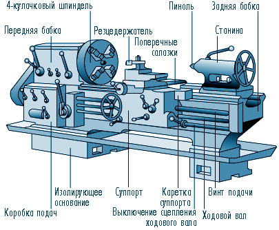
1E61MT Location of the main components and controls of the machine

Location of machine controls 1e61mt
List of controls for the 1E61MT lathe
- Turning on the electric oil pump and connecting to an external power supply
- Switching on the emulsion pump
- Stop for starting, stopping and reversing the spindle
- Switching spindle speed
- Turning on the front headstock
- Snaffle and mechanism for eightfold increase in thread pitches
- Norton cone gear shifting
- Inclusion of metric and modular, inch and pitch or fine threads
- Multiplier feed mechanism or thread pitches
- Turning on the lead screw or lead shaft
- Handwheel for manual longitudinal movement of the carriage
- Cross support movement
- Moving the upper slide of the caliper
- Tool holder
- Inclusion of longitudinal or transverse feeds
- Turning on the lead screw nut
- Turning the falling worm on and off
- Fastening the caliper carriage to the frame
- Mounting the tailstock to the frame
- Moving the tailstock quill
- Tailstock quill fastening
- Lateral displacement of the tailstock housing
- Longitudinal automatic stop
- Cross feed automatic stop
- Rigid fixation of the uterine nut of the lead screw
- Switching on local lighting
- Quick removal of the cutter from the workpiece
1E61MT Kinematic diagram of a screw-cutting lathe

Kinematic diagram of a screw-cutting lathe 1e61mt
1E61MT Location of gearbox control handles

Location of gearbox control handles 1e61mt
The purpose of the control handles of the gearbox of the lathe
- Norton cone handle
- Guitar
- Headstock
- Inch and pitch threads
- Metric and modular threads
- Precise threads
- Multiplier feed handle
- roller
- lead screw
- Shift knob
- Tuning knob
1E61MT Scheme for tuning the guitar of a screw-cutting lathe 1e61mt

Lathe guitar tuning scheme 1e61mt
Scheme for tuning the guitar of a screw-cutting lathe
- a) Tuning the guitar to precise, normal, metric and modular carvings
- b) Tuning the guitar to normal, inch and pitch cuts
1E61MT Headstock of a screw-cutting lathe

Headstock of a screw-cutting lathe 1e61mt
Features of disassembly and assembly of the 1E61MT machine during repair
When disassembling the machine in case of repair or for any other reason, pay attention to the following:
- Disconnect the machine from the mains before proceeding with its disassembly
- disconnect pressure 3 and drain 13 tubes from the oil system (Fig. 21)
Before remove spindle head from the machine you need:
- remove the V-belts from the gearbox pulley
- unscrew the four Ml4 bolts securing the headstock to the bed (two bolts are inside the housing at the back of the headstock)
- remove the headstock from the bed
For removing V-belts headstock, it is necessary to remove the headstock spindle, and then the hub with the pulley sitting on it.
To take out the spindle 1 from the body of the headstock, it is necessary to remove the top cover 24, the back covers 12, 13 and the front flange 2. Together with the back cover, remove the snaffle roller 8. Unscrew the nut 10 from the end of the spindle, loosen the screw 11 first. 23 by screwing onto the sleeve 25, loosen the insert 26, thereby increasing the gap between the spindle and the insert. Do the same with the rear plain bearing. After unscrewing the locking screws of the snaffle gears 15 and sorting 4. Then, using a lead hammer, knock out the spindle with weak blows.
To remove the pulley with the hub it is necessary to remove the rear flange 14 from the body of the headstock, loosen the lock screw 6 and unscrew the nut 7, then remove the snaffle 9. Next, it is necessary to loosen the lock screw 20, unscrew the nut 21, loosen the set screws 19 and 16. After that, hit the end face of the sorting gear 22 knock out the hub 18 together with the pulley 17.
Remove drain rubber tube 5 and remove the V-belts. Assembly of the headstock will occur in reverse order.
Disassembly of the remaining components of the machine, due to the clarity of dismantling, does not require explanation.
Electrical equipment of the machine

The electrical circuit of the lathe 1e61mt
The machine is equipped with 3 three-phase squirrel-cage asynchronous electric motors for voltage 220/380 V:
- D1 - main electric motor type AOS 51/4, version Shch-2, power 4.5 kW, 1335 rpm
- D2 - electric lubrication pump type PA-22 with a power of 0.125 kW, 2800 rpm
- D3 - electric pump for supplying coolant type PA-22 with a power of 0.125 kW, 2800 rpm
The electrical equipment of the machine is mounted on a voltage of 380 V.
If necessary, a machine with electrical equipment for a voltage of 220 V can only be made by special order.
1E61 High precision screw-cutting lathe. Video.
The main technical characteristics of the lathe 1E61MT
| Parameter name | 1E61MT | 1E61PM | UT61PM |
|---|---|---|---|
| Main parameters of the machine | |||
| Accuracy class according to GOST 8-82 | IN | P | P |
| The largest diameter of the workpiece processed above the bed, mm | 320 | 320 | 320 |
| The largest diameter of the workpiece processed over the support, mm | 188 | 170 | 170 |
| The greatest length of the installed part RMTs, mm | 710 | 710 | 750 |
| The greatest distance from the center axis to the edge of the tool holder, mm | 185 | 175 | 175 |
| Distance from the spindle axis to the frame guides (height of centers), mm | 170 | 175 | 175 |
| Spindle | |||
| Spindle hole diameter, mm | 32,5 | 30 | 32 |
| Diameter of the bar passing through the hole in the spindle, mm | 32 | 25 | |
| Spindle speed, rpm | 35..1600 | 35,5..1800 | 40..2000 |
| Number of forward/reverse spindle speeds | 12 | 18 | 18 |
| Center in the spindle according to GOST 13214-67 | Morse 5 | Morse 5 | Morse 5 |
| Spindle end according to GOST 12595-72 | 5K | 5K | |
| Spindle braking | There is | There is | There is |
| Spindle lock | There is | There is | There is |
| Spindle overload protection | There is | There is | There is |
| Submissions | |||
| The greatest length of the stroke of the caliper (carriage) - longitudinal movement, mm | 640 | 710 | 710 |
| The greatest transverse movement of the caliper, mm | 200 | 230 | 230 |
| Longitudinal movement of a support on one division of a limb, mm | 0,2 | 0,1 | 0,1 |
| Cross movement of a support on one division of a limb, mm | 0,02 | 0,02 | 0,02 |
| The greatest movement of the upper caliper (cutting sled), mm | 140 | 140 | 140 |
| Movement of the upper support by one division of the limb, mm | 0,02 | 0,02 | 0,02 |
| Number of feeds of longitudinal / transverse caliper | 21 | 40 | |
| Longitudinal feed limits, mm | 0,04..6 | 0,018..1,1 | 0,018..1,1 |
| Transverse feed limits, mm | 0,012..1,87 | 0,01..0,625 | 0,01..0,625 |
| Number of metric threads to be cut, mm | 22 | 35 | |
| Number of cut modular threads, mm | 19 | 31 | |
| Number of cut threads inch, mm | 15 | 26 | |
| Limits of pitches of metric threads, mm | 0,35..12 | 0,1..56 | 0,1..56 |
| Limits of pitches of modular threads, module | 0,3..6 | 0,1..28 | 0,1..28 |
| Limits of pitches of inch threads, threads / inch | 20..3,0 | 30..3,0 | 60..3,0 |
| Speed of fast movements longitudinal / transverse, m/min | No | No | No |
| Height of the cutter installed in the tool holder, mm | 20 | 20 | 20 |
| tailstock | |||
| The greatest movement of the quill, mm | 100 | 100 | 100 |
| The price of dividing the limb of the tailstock, mm | 1 | 0,05 | 0,05 |
| Center in quills according to GOST 12595-72 | Morse 3 | Morse 3 | Morse 3 |
| Cross displacement of the tailstock, mm | ±5 | ±5 | ±5 |
| Drill diameter when drilling steel, mm | 12 | ||
| Drill diameter when drilling cast iron, mm | 15 | ||
| Electrical equipment of the machine | |||
| Number of electric motors on the machine | 3 | 3 | 4 |
| Power of the electric motor of the main drive, kW | 4,5 | 2,7/ 4,4 | 3,2/ 5,3 |
| Cooling pump motor power, kW | 0,125 | 0,12 | 0,12 |
| Lubrication pump motor power, kW | 0,125 | 0,08 | 0,09 |
| Fan motor power, kW | No | No | 0,18 |
| Dimensions and weight of the machine | |||
| Machine dimensions (length width height), mm | 2191 x 930 x 1500 | 2290 x 1150 x 1365 | 2110 x 1050 x 1395 |
| Machine weight, kg | 1650 | 1670 | 1810 |
The production of universal screw-cutting lathes of the IT-1M series was carried out by the Ivanovo Machine-Tool Plant, Lugansk region. This type of equipment is designed to perform a wide range of turning operations. To get acquainted with its characteristics and capabilities, you should study the layout of the model.
Design and features of the machine
The main scope of the IT-1M model is the turning of a workpiece fixed in a chuck, faceplate or centers. The screw-cutting unit has a classic layout, is distinguished by intuitive operation and reliability.
To increase the functionality, the manufacturer offers a number of additional devices. With their help, you can do milling the surfaces of workpieces, drilling, forming keyways and boring. However, it should be borne in mind that the IT-1M model is designed to perform turning operations.
Among the design features of the equipment, the following can be distinguished:
- rigid stand. For its manufacture, cast iron is used, the body is formed by casting. To increase stability, there are stiffeners;
- polished guides. They have a prismatic shape, which contributes to the smooth running of the carriage and the tailstock;
- improved design of spindle supports. It has a double-row roller bearing, which has an adjustable clearance;
- the presence of a recess in the frame. Thanks to it, it is possible to process large-diameter products.
If the jaws extend beyond the outer section of the chuck, a special guard must be used. It is also worth noting the convenient location of the plunger pump of the lubrication system in the IT-1M machine. It is located in the headstock housing.
When activating the longitudinal pass function, a hold-down must be used. Thanks to him, the quality of processing of the product is improved, the labor intensity of the process is reduced.
Technical specifications

Since the machine of the IT-1M series belongs to the category of professional equipment, its operational parameters should be considered in more detail. To do this, it is recommended to familiarize yourself with the passport, as well as study the actual characteristics of the model.
Initially, the equipment was designed for operation in small rooms. Therefore, its dimensions are quite small and amount to 216.5 * 96 * 150 cm. However, the relatively large mass of 1140 kg contributes to increased structural stability when processing large-diameter workpieces. At the same time, the possibility of using cutters made of special grades of steel is considered individually for each case.
The IT-1M lathe has the following technical characteristics:
- maximum allowable dimensions blanks. When fixed on the frame - up to 40 cm. For fixing over the caliper, this parameter cannot exceed 22.5 cm. If a notch is used, the limit is up to 55 cm;
- the length of the part varies from 100 to 140 cm;
- the spindle head has a through hole with a diameter of 38 mm. At the same time, a bar with a cross section of up to 36 mm can be inserted into it;
- the number of switching speeds of the spindle speed - 12;
- rotational speed of the working head - from 18 to 1250 rpm;
- the carriage has a stroke of 90 to 130 cm;
- IT-1M machine support stroke - up to 23.5 cm;
- longitudinal feeds have 50 feet;
- displacement of the tailstock quill - up to 9 cm.
The power of the main drive electric motor is 3 kW. The same parameter of the plunger pump is 0.12 kW. The scheme of the IT-1M model has overload protection in case of longitudinal displacement, as well as a handle locking mechanism.
The video shows an example of the operation of equipment connected to a 220 V network:
IT-1M machine characteristics
IT-1M – Screw-cutting lathe

Specifications:
It-1m model machines are designed to perform a variety of turning and thread-cutting work in a chuck. on the faceplate and in the centers. The machine performs turning, boring, trimming, drilling and cutting of metric, inch, modular and pitch threads.
Accuracy class according to GOST 8-82E N
The largest diameter of the processed workpiece, mm:
- over bed 400
- above the notch 550
- above the caliper 225
The greatest length of the workpiece (RMC), mm 1000, 1400
The greatest length of processing in a recess, mm 300
Center in the spindle according to GOST 13214-79 Morse 5AT8
Spindle end according to GOST 12593-72 6K
The diameter of the bar passing through the hole in the spindle, mm 36
height of the cutter installed in the tool holder, mm 25
Number of spindle speeds 12
Spindle speed limits, min-1 28. 1250
Number of longitudinal / transverse feeds 50 / 50
Feed limits, mm/rev:
- longitudinal 0.05. 6.0
- transverse 0.025. 3.0
Thread pitch:
- metric, mm 0.25. 112
- modular, module 0.25. 56
- inch, threads per inch 56. 1
- pitch, pitch 56. 1
Overall dimensions of the machine, mm:
- length (corresponds to RMC) 2165, 2585
– width 960
– height 1500
Weight of the machine without accessories and fixtures (corresponds to RMC), kg. 1140, 1330
Screw-cutting lathe IT-1M
Lathe IT 1M is a lightweight universal metalworking equipment, which is a compact modification of the stationary IT-1GM unit. This machine corresponds to the accuracy class "H9raquo; in accordance with the provisions of GOST No. 8-82E.

In the article, we will consider the purpose and functionality of the IT1M lathe, study its design and technical characteristics, and also present feedback from people who have experience in operating this equipment.
1 Purpose, functionality
IT-1M was produced at the Ivanovo Machine Tool Plant from 1970 to 1995. This equipment was widespread during the Soviet era and can still be found in production today. This unit is capable of performing the following technological operations:
- turning;
- boring;
- drilling;
- facing;
- threading (pitch, modular, metric inch).
The machine is capable of performing turning and screw-cutting work in three positions - on the chuck, in the center and on the faceplate. It is used for milling grooves, external and internal grinding, boring of hull structures. The machine has two shaping movements: the first is the rotational movement of the part, the second is the translational movement of the working tool.

Among the characteristic features of the IT-1M model, we highlight:
- flat shape of the guides made of hardened steel with a polished surface, which ensures the rigidity of the structure and minimal friction when moving the working units;
- box-shaped bed with internal transverse stiffeners;
- the presence of 12 speed modes of the spindle, which is located inside the headstock, which eliminates the possibility of mechanical damage to the assembly;
- adjustable supports - the front one is mounted on double-row roller bearings, the rear one - on radial ones;
- the presence of an automatic coolant supply system and an auxiliary drive for the plunger pump;
- the ability to adjust the transverse position of the tailstock, which allows turning structures with a low taper rate;
- the bed is equipped with a seat for the installation of a supporting bridge, when equipped with a machine that can process parts with a diameter of up to 550 mm.
IT-1M is a lightweight model of turning equipment designed for use in mobile workshops. The weight of this unit is only 1140 kg, it is able to operate from a generator connected to a car engine.
to the menu
1.1 IT-1M screw-cutting lathe in operation (video)
1.2 Design features
The IT-1M screw-cutting lathe consists of the following structural units:
- Support pedestals.
- Gearbox.
- Front grandma.
- Control panel for electrical equipment.
- Cartridge limiter.
- Caliper.
- Rear grandma.
- Apron.
- Carrying frame.
- Reducer.
- Coolant supply system.
- Cabinet with electrical equipment.

Scheme of the machine IT-1M
The dimensions of the unit are 216 * 150 * 96 cm. The machine is equipped with two independent electric motors: X14-22M - the drive of the plunger coolant pump (power 120 W) and the main engine - 4AM100S4, with a power of 3000 W, producing up to 1410 spindle revolutions per minute.
Both engines and all electrical equipment are capable of operating from 220 and 380V networks. The choice of operating voltage is carried out by means of a packet-cam switch mounted in the control panel (No. 4). The console also contains switches for lighting the working area, a coolant pump and a main drive switch. The cooling system of the machine is represented by supply pipes and a plunger pump located inside the reservoir with coolant. The tank itself is located in the right support pedestal.
The tailstock in IT-1M is installed on guides along which the structure moves. After installation in the desired position, the headstock is fixed with a support nut. The flywheel is responsible for moving the quill, it has a millimeter scale to control the level of extension of the quill.

Kinematic scheme of the machine
The caliper in this mechanism consists of the following parts:
- sled (longitudinal and transverse);
- carriage;
- swivel type holder.
The working movement is transmitted through the chain engine - gearbox - feed shaft - caliper, while the handle of the control screw is blocked by the clutch immediately after the activation of the drive shaft, which does not allow the shaft and the screw to be in the active state at the same time. This guarantees the safety of the operator.
to the menu
2 Specifications
Consider the technical characteristics of the IT-1M model, starting with its general parameters:
- accuracy class (in accordance with GOST No. 8-82) - H;
- processing diameter over the statin - up to 400 mm;
- diameter of processing over a support — 225 mm;
- processing diameter above the notch in the frame - 550 mm;
- maximum length of parts - up to 1400 mm.
- through hole diameter — 38 mm;
- bar diameter - 36 mm;
- number of rotation speed modes - 12 pcs (including reverse);
- rotational speed - from 18 to 1260 rpm;
- type of inner cone - Morse-5;
- spindle taper class (in accordance with GOST No. 12593) - 6K;
- Spindle brake function.

Wiring diagram IT-1GM
- maximum carriage travel length - 1300 mm;
- caliper transverse travel - up to 235 mm;
- number of feeds: longitudinal - 50, transverse - 50;
- feed limits: longitudinal - from 0.05 to 6, transverse - from 0.025 to 3 mm / rev.
A tailstock with an internal Morse taper 4 is installed on the machine. The power of the main electric drive is 3000 W, the cooling pump drive is 120 W. Unit weight - 1140 kg.
to the menu
2.1 Spindle problems and repair features
The IT-1M screw-cutting lathe is represented on the secondary market by models produced in the 80-90s, which have worked out a large part of their operational life. In such units, the spindle often makes itself felt, which fails due to wear of the necks, cone and end holes.
In case of wear, the neck must be machined, ground and polished with GOI paste. In the absence of grinding equipment, the neck is processed on a turning unit using a spring cutter - you need to remove the thinnest layer of the skin, and then polish the surface of the spindle with paste. If these operations have already been performed, and a further reduction in the diameter of the spindle is unacceptable, the assembly must be replaced.
Spindle taper problems are often caused by the machine operator not paying due attention to cleaning the clogged taper, causing the seat to lose its original shape. The taper configuration can also be damaged due to slippage of the turning tool shank.

Disassembled spindle assembly IT-1M
Checking the dimensions of the cone is carried out according to the caliber, it must first be cleaned with sandpaper and polished. If the check indicates an irregular shape of the seat, it is recommended to bore it under the adapter sleeve, and already in the sleeve itself form an internal cone of a standard configuration.
The boring itself should be done after the spindle bearings have been run in. You will need to tighten them up and check the runout, after which you need to make sure that the spindle meets the GOST accuracy standard. If the design is in a satisfactory condition, you can dismantle the protruding mandrel and start boring the cone.
Boring is carried out as follows. The cutter fitted in height is installed in the center of the mounting hole, then the angle of inclination of the cutter slide is adjusted. Further, the surface of the cone is covered with turpentine or an arbitrary lubricant and boring begins. Upon completion of the boring, the surface of the cone is ground and polished.
to the menu
2.2 Reviews
We bring to your attention reviews of the IT-1M screw-cutting lathe from the owners of this equipment.
V. S. Prokhorov, 59 years old:
I worked half my life on this machine at the factory. This is a hardy and reliable unit, which has no analogues among modern equipment. The machine copes with the processing of parts made of metal of any hardness, including hardened steel.
P. L. Bichurin, 37 years old:
Of course, in terms of ergonomics, productivity and functionality, IT-1M is inferior to modern machines, but if you are looking for a trouble-free and unpretentious machine for production, this is the best choice. There are two of these in the metalworking shop - excellent workhorses.
IT-1M - lightweight screw-cutting lathe for mobile workshops
Pipe bender manual TR and other brands - we consider the types of this device 
In this article, we will look at various mechanical pipe benders that can be used by hand, using only muscle.
Types of welding machines - an overview of popular models 
The article will tell you what special equipment it makes sense to purchase if you plan to work on.
Band saw machine (band saws)
Non-ferrous metals and alloys
Structural steels and alloys
IT-1M, IT-1GM Lightweight universal screw-cutting lathe
diagrams, description, characteristics
Universal screw-cutting lathes IT-1M, IT-1GM were produced at the enterprise Ivanovo Machine Tool Plant in the village of Ivanovka, Luhansk region (formerly Voroshilovograd) in Ukraine.
Screw-cutting lathes. General information
Lathes are divided into universal and specialized. Universal machines are designed to perform a wide variety of operations: processing of external and internal cylindrical, conical, shaped and end surfaces; cutting of external and internal threads; cutting, drilling, countersinking and reaming holes. On specialized machines, a narrower range of operations is performed, for example, turning smooth and stepped shafts, rolling rolls, wheelset axles railway transport, various types of couplings, pipes, etc. Universal machines are divided into screw-cutting and turning. Lathes are designed to perform all turning operations, with the exception of threading with cutters.
Our industry produces various models of lathes and screw-cutting lathes - from desktop to heavy ones. The largest diameter of the machined surface on Soviet machines ranges from 85 to 5000 mm, with a workpiece length from 125 to 24,000 mm. Some screw-cutting lathes are equipped with copiers that allow processing complex contours without special shaped cutters and combined boring tools, and also greatly simplify the setup and adjustment of machines.

Structural diagram of a screw-cutting lathe
- rotational movement of the workpiece (B 1) along the chain: electric motor 1 - spindle 2 with setting link i v
- translational movement of the tool (P 1 and P 2) along the chain: spindle 2 - running shaft 4 (when turning) or spindle - lead screw 3 (when threading) with adjustment links i v and i kp

The main dimensions of the screw-cutting lathe
The main parameter of the screw-cutting lathe is the largest diameter, D, of the workpiece to be machined over the bed. The gap between the horizontal plane of the guides and the diameter of the workpiece D is not more than 0.04D. Diameter D is approximately equal to twice the height of the machine centers.
GOST 440-57 provides for a number of sizes of screw-cutting lathes with D values from 100 to 6300 mm, built according to the law of geometric progression with a denominator φ = 1.26 (with slight rounding).
Another main parameter of the machine is the largest distance between its centers, which determines the maximum length of the workpiece. It is determined when the tailstock is shifted (without hanging from the guides) to the right extreme position. Machine tools with the same largest diameter of the workpiece being processed can have different center-to-center distances within the limits provided for by GOST 440-57. For example, machines with the largest workpiece diameter of 400 mm are made with the largest distance between centers of 700, 1000 and 1400 mm. For most heavy lathes, the largest center distance is not specified.
An important dimension of the machine is also the largest diameter of the workpiece to be machined above the support D1. It must be no less than provided for in GOST 440-57.
In addition to these basic parameters of screw-cutting lathes, GOST 440-57 establishes the maximum number of spindle revolutions, the largest diameter of the bar passing through the spindle hole, the size of the spindle center (Morse taper or metric number), the maximum height of the cutter and the maximum allowable weight of the machine (without electrical equipment ).
Type of screw-cutting lathes
The machine tool industry produces screw-cutting lathes with the largest diameter of the workpiece being processed within 160-1250 mm and the largest distance between centers up to 12,500 mm.
IT-1M, IT-1GM Universal screw-cutting lathe. Purpose, scope.
Specialized light-weight screw-cutting lathes IT-1M, IT-1GM are designed to perform a variety of turning and screw-cutting operations in a chuck, on a washer plan and in centers.
The machine performs turning, boring, trimming, drilling and cutting of metric, inch, modular and pitch threads.
In the presence of special devices on the machines, it is possible to mill planes, keyways and other grooves, boring small body parts, external and internal grinding.
The IT-1M model is designed for use in mobile repair shops, the IT-1GM model is a stationary machine.
The supply voltage to the IT-1M machine is supplied from a generator, which is driven from the car engine through the transmission.
The accuracy class of machine tools is H according to GOST 8-82E.
Design features of the IT-1M, IT-1GM lathe
The machine bed is cast construction, box-shaped with transverse ribs. For the possibility of processing products with a diameter of up to 550 mm, the bed has a recess with a bridge inserted into it.
Two prismatic and two flat guides are subjected to heat treatment followed by grinding.
In the headstock there is a spindle assembly, a step increase link, a thread and feed reverse, as well as a drive for the movement of replaceable gears and a feed box.
In the spindle bearings, the following are used: in the front - a double-row roller bearing with adjustable radial clearance, in the rear - a deep groove ball bearing.
The spindle has twelve speeds.
The tailstock moves along the guides of the bed.
For turning conical surfaces with a small taper, the body of the tailstock is displaced in the transverse direction relative to the axis of the machine in both directions along the guide tooth.
The feed box receives movement from the headstock of the machine through interchangeable gears and provides cutting of metric, inch, modular and pitch threads.
The chuck guard is used when working with the jaws extended beyond the outside diameter of the chuck.
On the IT-1M machine, a clamp is provided, which secures the fence in the through position.
Lubrication of the machine is carried out using a plunger pump mounted on the headstock housing.
Modifications of the screw-cutting lathe IT-1M, IT-1GM
- IT-1M (RMTs = 1000 mm) - a specialized lightweight machine for mobile workshops
- IT-1M-01 (RMTs = 1400 mm) - a specialized lightweight machine for mobile workshops
- IT-1GM (RMTs = 1000 mm) is a specialized lightweight stationary machine
- IT-1GM-01 (RMTs = 1400 mm) - a specialized lightweight stationary machine
Overall dimensions of the working space of the screw-cutting lathe IT-1M, IT-1GM

Landing and connecting bases of the IT-1M, IT-1GM screw-cutting lathe. Spindle

General view of the IT-1GM screw-cutting lathe

Location of the components of the IT-1M, IT-1GM lathe

List of components of the lathe LT-10M, LT-11M
- Cabinets and cooling - IT-1M.12.000; IT-1M.14.000*
- Feed box - 16B20P.070.000-03
- Grandma front - IT-1M.22.000
- Control panel - IT-1M.81.000
- Cartridge guard - IT-1M.78.000; IT-1GM.79.000**
- Caliper - IT-1M.60.000
- Grandma rear — IT-1M.40.000
- Apron - 16B16P.061.000.01
- Bed - IT-1M.10.000; IT-1M.11.000*
- Reducer - IT-1M.20.000
- Lubrication unit - IT-1M.75.000
- Electrical cabinet — IT-1GM.82.000**
* For a machine with a distance between centers of 1400 mm.
** For stationary machine model IT-1GM.
The location of the controls for the IT-1GM lathe

List of controls for the IT-1M, IT-1GM lathe
- Spindle speed shift knobs
- Handle for setting the feed rate, thread pitch and disabling the box mechanism
- Handle for setting feeds or type of threads (metric, inch, modular, pitch)
- Handle for setting feeds and thread pitch
- Feed switching block
- Thread Pitch Switching Knob: "Standard Pitch", "Increased Pitch"
- Handle for setting right or left threads
- The handle of enumeration (switching of frequency of rotation of a spindle)
- Spindle speed change table
- Voltage setting switch
- * Voltage switching unit (IT-1M)
- Cooling motor switch
- Automatic switch
- Chuck Guard Cover Clamp Screw
- * Light switch (IT-1M)
- Screen Rod Clamp Screw
- Handle for turning and clamping the tool holder
- Adjustable coolant nozzle
- Refrigerant pipe clamp screw
- The handle of the transverse movement of the caliper carriage
- Upper Carriage Handle
- Caliper Clamp Screw
- Quill clamp handle
- Tailstock Clamp Nut on Bed
- Quill extension flywheel
- Tailstock Lateral Offset Screw
- The handle for the mechanical movement of the carriage and the cross slide of the caliper
- Leadscrew Nut Lever
- Light fixture clamp handle
- Rack and pinion button
- Flywheel of longitudinal movement of a support
- The handle of inclusion of rotation, reversal and braking of a spindle
- * Stop button (IT-1M)
- * Signal lamp (IT-1M)
- Precondition button
- * Voltage setting switch (IT-1M)
Kinematic diagram of a screw-cutting lathe IT-1M, IT-1GM

Electrical circuit diagram of the IT-1M, IT-1GM lathe

- Power supply: 380 V, 50 Hz
- Circuit breaker
- Main drive motor
- Cooling motor
- plug connection
- Fuse
- Control transformer
- Voltage presence plug lamp
- local lighting
- Control button "All Stop"
- Zero protection
- Thermal protection
- Main drive Right
- Main drive Left
- Cooling management
Screw-cutting universal machine IT-1M. Video.
The TV series of turning units consists of universal machine tools, which were widely used in educational polytechnic institutions and schools during the Soviet era. This is a hardy and unpretentious equipment in operation, which can be found in operation today.
This article presents the TV-x series lathes, we will consider such models as TV-4 Shkolnik, TV-6, TV-7 and TV-16. Their technical characteristics, design features will be studied, as well as tips on the features of operation and Maintenance aggregates.
1 Design of TV lathes
TV screw-cutting lathes are classified as educational equipment. These units are capable of the following types technological operations:
- boring and groove;
- trimming ends;
- segment;
- formation of metric thread;
- drilling, countersinking.
All TV machines have a similar layout, they consist of the following main units:
- The front and rear pedestals (have a U-shape), performing the function of supporting surfaces on which the machine bed is fixed. Longitudinal and transverse stiffening ribs give additional mechanical strength to the pedestals.
- Bed - all structural elements of the machine are fixed on it. It has a box shape and is equipped with two guides, on the front of which the carriage moves, on the back - the tailstock.
- The tailstock is fixed on the left right side of the frame, the back parts of long workpieces or a working tool (drills, reamers, countersinks) are fixed on it.
- An electric motor and a feed box that transmits the rotation of the spindle to the running shaft of the machine. A V-belt box is installed on the machines of the TV series.
- The headstock is the main working body of the machine, in which the spindle and the fastening unit are located, which fix the workpiece and transmit the rotation of the drive to it.
- The caliper, cutter and tool holder are the mechanisms by which the workpiece fixed in the stocks is processed. The caliper is a mechanism for moving the cutter to a predetermined position.
The wiring diagram of TV units is extremely simple. The units are equipped with the following equipment - an asynchronous type electric motor (runs on three-phase current), magnetic starters, fuses and an electrical panel, on which the motor switch and buttons for controlling the lighting of the working area are displayed.
The presence of a magnetic starter distinguished TV machines from analogues of that time. The starter is a system that prevents the machine from turning on after a power failure, which greatly increases the safety of equipment operation.
1.1 TV-4 lathe - operating experience (video)
2 Overview of TV machines - differences, specifications
The first mass-produced model is TV-2. This unit has three feeds and is capable of cutting three types of threads. TV-2 was carried out in two versions - large-sized (with a cast headstock cover) and compact, with a stamped cover.

Specifications TV-2:
- center height - 100 mm;
- caliper travel: longitudinal - 250, transverse - 100 mm;
- spindle class - KM2, hole diameter - 15 mm.
The TV-2 unit was equipped with a 500 W electric drive with a spindle speed of 900 rpm.

More modern model was a modernized screw-cutting lathe TV-4, which had an identical compact version TV-2 design, but differed in terms of technical characteristics. The TV-4 lathe is still produced in our time, the plant supplies this model to the market. industrial equipment"MASGO" (Rostov).
TV-4 screw-cutting lathe - specifications:
- center height - 108 mm, distance between centers - 350 mm;
- diameter of processing over a support — 100 mm;
- caliper travel: longitudinal - 300, transverse - 100 mm;
- spindle class - KM2, hole diameter - 16 mm.
TV-4 differs from its predecessor by increased engine power up to 600 W, the maximum spindle speed in it has increased to 1500 rpm. In total, 6 fixed speeds are provided - at 710, 500, 375, 230, 160 and 120 rpm.
See also: technical characteristics, operation, adjustment and repair of screw-cutting lathes.

The next modification, the production of which began in 1970, was the TV-6 screw-cutting lathe. This unit is an almost complete copy of the TV-4, with the exception of small details - elongated carbolite handles, and the presence of an electrical panel on the right pedestal, while in the TV-4 there was no electrical panel, and the switches and starters were located in a metal box located above the motor. Specifications in the TV-6 have undergone minimal changes - the drive power has increased to 1.1 kW, and the spindle speed has decreased to 1410 rpm.

The TV-7 lathe has serious differences from the 6th version of the lathe. It removed 2 handles on the headstock - it is necessary to switch speeds by changing the position of the belt, and expanded the functionality of the device, the machine was able to make 6 types of threads and acquired three additional feed steps.
Specifications:
- center height - 120 mm, distance between centers - 330 mm;
- diameter of processing over a support — 100 mm;
- caliper travel: longitudinal - 300, transverse - 110 mm;
- supply: 0.1, 0.12, 0.16, 0.2, 0.24, 0.32.
The drive power remained unchanged - 1.1 W, but the speed decreased to 920 rpm. To date, an improved modification is being produced - the TV 7M machine, with a rotation speed of 1410 rpm.

The most common version of the TV series equipment was the TV16 screw-cutting lathe, which is a company of the Czechoslovak TOS MN-80 unit. The only difference between them was the mounting sockets in the tool holder - the original had square holes, and the domestic counterpart had standard grooves.
The TV-16 lathe has the following characteristics:
- center height - 90 mm, distance between centers - 330 mm;
- diameter of processing over the caliper - 160 mm;
- caliper travel: longitudinal - 260, transverse - 100 mm;
- spindle class - KM3, hole diameter - 18 mm;
- feed: from 0.01 to 0.5 (19 positions).
To date, this model is not produced, on sale you can find used units worth 30-40 thousand rubles, or pick up new machines that are suitable for the characteristics.