TC - 11233753.017-2015
ROUTING
Laying cables in the ground
Introduction date 2016-01-01
Developed by: OJSC - Association "Montazhavtomatika"
Considered: At the technical council of OJSC - Association "Montazhavtomatika" 10/26/2015
Approved by: Technical Director of OJSC - Association "Montazhavtomatika" Sirotenko V.S. 11/10/2015
INSTEAD OF: Developed for the first time
1 area of use
1 area of use
1.1 The technological map was developed in accordance with the requirements of STO 11233753-004-2011, STO 11233753-008-2012.
1.2 Technological maps should be used when performing installation work in accordance with section 5.7.5 of SP 48.13330.2011.
1.3 This flow sheet applies to the installation of control, control, communication and power cables up to 10 kV in the ground.
1.4 When linking a technological map to a specific object, the requirements set forth in the map can be supplemented or changed taking into account the features of the object, special requirements working documentation and working conditions. Features of the application of the card are recommended to be given as part of the PPR or a technological note replacing it.
2 Normative references
In this technological map There are links to the following regulatory documents:
GOST 12.1.051-90 Safety distances in the security zone of power lines with voltage over 1000 V;
SP 45.13330.2012 Code of Practice. Earthworks, foundations and foundations. Updated edition of SNiP 3.02.01-87;
SP 48.13330.2011 Code of Practice. Organization of construction . Updated edition of SNiP 12-01-2004.
3 Terms, definitions and abbreviations
In this technological map, the following terms are used with their respective definitions and abbreviations:
3.1 VL: High voltage line;
3.2 FOCL: Fiber-optic communication lines;
3.3 UCP: Crane load limiter;
3.4 OK: Optical cable;
3.5 outdoor switchgear: outdoor switchgear;
3.6 PPR: Project for the production of works;
3.7 w.h.: Working drawings;
3.8 E2: Electrician of the second category;
3.9 E3: Electrician of the third category;
3.10 E4: Electrician of the fourth category;
3.11 E5: Electrician of the fifth category.
4 General rules for laying cables in the ground
4.1 Requirements for the cable and its protection
For cable lines laid in the ground, armored cables should be used predominantly. The metal sheaths of these cables must have an outer jacket to protect them from chemical attack. If unarmored cables are being laid, then asbestos-cement or PVC pipes must first be laid, which will reliably protect it from accidental mechanical damage during subsequent excavations. If the cable is armored, then its use will also require the laying of pipes at the intersection with railway and tram rails, highways and dirt roads, under the carriageways of streets, at intersections with underground structures and other cables so that the ends of the pipes come out 1 m outside the intersection, as well as when entering the cable into a building or structure.
The depth of the cable laying is determined by the r.ch. and should not deviate from the accepted value by more than ± 10 cm. During the cable laying process, this value must be systematically monitored. As a rule, the depth of the trench should be at least 0.8 m in order to ensure that the cable is laid at a depth of at least 0.7 m from the soil surface, or from the planning mark. There should be no water at the bottom of the trench. At intersections and approaches to engineering structures and natural obstacles, the cable can be laid in a section up to 5 m at a depth of at least 0.5 m using cable protection with pipes.
Pipes (asbestos-cement, non-pressure plastic, concrete, ceramic, cast iron) should be used to protect cables, while the diameter of the pipes must be at least one and a half times the outer diameter of the cable.
In places where mechanical damage to cables is likely, they should be protected by reinforced concrete. slabs with a thickness of at least 50 mm, or ordinary bricks laid in one layer across the route. With a cutter width of the earth-moving mechanism less than 250 mm, and also for one cable - along the route.
Instead of brick or reinforced concrete. slabs above the cable line up to 20 kV, except for cable lines above 1 kV, supplying electrical receivers of the 1st category, it is allowed to use signal plastic tapes along the powder with a thickness of 250 mm in trenches with no more than two cable lines. It is not allowed to use tapes at the intersections of cables with utilities and above cable boxes at a distance of 2 m in each direction from the crossed communication or box, as well as at the places where lines approach switchgears and substations within a radius of 5 m.
With the consent of the owner of the lines, it is allowed to expand the scope of signal tapes.
For laying over one cable, SL-150 tape is used, over two - SL-300 and then with a width that is a multiple of 150 mm (SL-450, SL-600, SL-750, SL-900).
If the ends of the cable at the splicing points fall on an inclined section of the route (slope up to 20 °), it is necessary to level the bottom of the trench in this place at a length of 8.3 meters so that the coupling is on a horizontal platform.
When entering buildings and structures through pipes, the cable at the inlet and outlet of the pipe must be tightly wrapped with resin tape over a length of 7-10 cm, and the gaps between the cable and the pipe are sealed with tarred tow and putty (80% chalk and 20% drying oil - by weight) .
Cables laid in the ground must be marked with identification marks.
Identification marks are installed (or applied):
- on the turns of the route;
- in places of installation of couplings;
- at the intersection with underground structures;
- at entrances to buildings and every 100 m on straight sections of the route.
Signs are applied in the form of inscriptions on the walls of permanent buildings or on special posts.
Track location cable line they are compared according to the plan with reference to its coordinates to existing permanent buildings or structures, and all deviations are included in the plan.
4.2 Cabling temperature
The laying temperature refers to the cable sheath temperature, not the ambient air temperature.
Upper allowable temperature: +50°С.
The lower allowable temperature value: minus 20°C - for a cable with a sheath made of polyethylene; minus 5°C - for a cable with a PVC sheath.
If during the day before laying the cable was in the open air, and the temperature dropped below minus 5 ° C, then laying is allowed only after the cable has been preheated.
After preliminary warming up, the cable laying should be carried out: at air temperature up to minus 15°C for no more than 1.5 hours; at air temperature in the range from minus 15°C to minus 25°C for no more than 1 hour. It is not recommended to carry out cable laying works at temperatures below minus 25°С.
Cable laying work is prohibited at ambient temperatures below minus 40°C.
Pre-heating of the cable is carried out inside heated rooms with an environment up to +40°C or in greenhouses or tents with infrared burners or heated with blowers at temperatures up to +40°C.
The duration of cable heating on drums in a warm room or in greenhouses should be selected in accordance with Table 1 below.
Table 1
|
Air temperature in the room |
5°С... +10°С |
10°С... +25°С |
25°С... +40°С |
|
Cable warm-up time, not less than |
4.3 Minimum cable bending radius:
During cable laying, its bending radii should not be less than 20xD, where D is the diameter of the cable along its outer sheath.
4.4 Stages of work
The whole procedure for underground cable laying includes several stages:
- selection and coordination of the cable laying route,
- marking and breakdown of the route,
- trench digging
- arrangement of bedding (pillow) from shallow earth without stones or sand,
- laying of protective pipes (if provided by the project),
- acceptance of a trench for cable laying,
- preparation of the cable for laying,
- cable laying (if the cable is laid in pipes, then pulling the cable in pipes),
- installation of couplings,
- backfilling the cable with fine earth without stones or sand,
- protection of the cable with red clay bricks or asbestos-cement boards,
- laying a signal and warning tape (if provided by the project),
- drawing up an act of hidden works,
- testing the cable line and backfilling the trench with soil.
All these electrical work must be carried out in the order in which they are listed.
4.5 Choice of route for cable laying
The cost of construction of cable lines and networks, their durability, as well as reliability and uninterrupted operation depend on the correct choice of the route. The route of underground cable lines is chosen based on the fact that the length of the cable laid between the given points is the smallest and ensures the convenience of cable laying and its further maintenance and operation.
Any electrical installation work related to excavation of the earth and laying the cable into the ground must be started only after the permits for cable laying have been received, since other engineering systems can be laid in the ground, and you can damage them or lay the cable in violation of existing standards.
If excavation are carried out in populated areas, then before they begin, the customer is obliged to issue a permit from the territorial administration to carry out the work provided for by the project and transfer it to the contractor.
The contractor is obliged, on the basis of a permit, to obtain a work order from the owner of the protected zone of underground utilities.
The order specifies:
- last name, first name, patronymic and position of the person responsible for the work;
- the term for the completion of construction work at the facility, linked to the submitted project for the production of works;
- organizations that are responsible for the restoration of road surfaces, replanting of green spaces and the timing of these works;
- organizations whose representatives must be called to the site before the start of earthworks.
Working documentation, an order for the right to carry out work and a copy of a written notification document must be located at the place of work.
Earthworks within the security zones of existing underground structures (power and communication cables, pipelines, etc.), as well as above-ground structures at their intersection (railways, highways), when laying a cable along the side of the road, etc., are allowed only if written permission of the organization operating these facilities, and in the presence of its representative, as well as the responsible work executor. The execution of works in such places must be agreed and reflected in the project documentation.
The construction organization is obliged not later than three days before the start of earthworks in writing to notify about the upcoming work, and one day before - to call representatives of interested organizations to the place of work to clarify the location of their structures and agree on measures to prevent damage to these structures. Prior to the arrival of representatives, excavation is prohibited.
The route before digging a trench should be inspected to identify places on the route containing substances that have a destructive effect on the cable sheath (salt marshes, lime, water, bulk soil containing slag or construction waste, areas located closer than 2 m from sewage, cesspools and garbage pits and so on.). If it is impossible to bypass these places, the cable should be laid in clean neutral soil in asbestos-cement pipes with their additional sealing. When filling the cable with neutral soil, the trench should be further expanded on both sides by 0.5-0.6 m and deepened by 0.3-0.4 m.
It is advisable to lay underground cable and cable ducts in settlements along the streets.
In cities and towns, the laying of cables in the ground (in trenches) is carried out along the impassable part of the streets (under the sidewalks), in the yards and technical lanes in the form of lawns, with shrub plantings, which have the least load of other underground structures (water supply, sewerage, gas pipeline, power cables etc.), so as to less disturb traffic during the work on laying the cable line and its operation.
Preliminary drilling should be carried out to accurately determine the underground structures intersected by the route of the laid communication cable or cable duct.
Pit holes should have a length of 1 m along the axis of the future trench. In the event that underground structures run parallel to the future route, the pits must be dug perpendicular to its axis every 20 m. The length of each pit must exceed the width of the designed trench on each side by at least 0.3 m.
The depth of the pits, if the structures being sought are not found, must exceed the depth of the trench by 0.2 m. The pitting must be carried out in the presence of a representative of the organization operating the underground structures.
Underground structures opened during drilling and during the development of trenches must be protected by a special box and suspended in the manner indicated in the working drawings.
If underground structures not specified in the working drawings are found during earthworks, work must be immediately stopped until the purpose of these structures is clarified and further work is agreed with their owners.
When laying in the ground in parallel with other operated cables or utilities near buildings and structures, clear distances (at least) must be observed;
- between cables up to 10 kV - 0.1 m (the same distance for parallel laying of newly laid cables);
- from 35 kV cables - 0.25 m;
- control cables or communication cables laid in one trench should be placed in parallel at a distance of 50 mm from each other without crossing (laying control cables close to each other is allowed);
- the distance between power cables up to 10 kV and control cables must be at least 100 mm, and between power cables and communication cables - at least 500 mm;
- distance between information cables SVT and power cables up to 1000 V - at least 0.7 m, power cables 6-10 kV - at least 1.5 m;
- from the cable to forest plantations - at least 3 m, from tree trunks - 2 m and from shrubs - 0.75 m (Figure 1);
- from the foundations of buildings and structures - 0.6 m (Figure 2);
- from pipelines, water supply, sewerage, drainage, low and medium pressure gas pipelines - 1 m (Figure 3);
- from high pressure gas pipelines and heat pipelines - 2 m (Figure 4);
- from the electrified railway - 10.75 m (Figure 5);
- from tram tracks - 2.75 m (Figure 6);
- from the road from the edge - 1 m;
- from the curb stone - 1.5 m (Figure 7);
- from the extreme wire of the 110 kV overhead line - 10 m (Figure 8);
- from the support of a 1 kV overhead line - 1 m (Figure 9);
- intersection cable routes(Figures 10, 11).
1 - cable up to 10 kV; 2 - foundation
Figure 2 - Laying cables near the foundation of the building and structures
1 - pipeline; 2 - cable up to 10 kV
Figure 3 - Laying cables parallel to pipelines, water pipes, sewerage, drainage, low and medium pressure gas pipelines
1 - tray; 2 - cable up to 10 kV
Figure 4 - Laying cables near heating mains and high pressure gas pipelines
1 - cable up to 10 kV; 2 - rail head
Figure 5 - Laying cables in parallel with an electrified railway
1 - rail head; 2 - cable up to 10 kV
Figure 6 - Laying cables in parallel with tram tracks
1 - roadbed; 2 - curb stone; 3 - cable up to 10 kV
Figure 7 - Laying cables parallel to the road
1 - VL support; 2 - cable 1-10 kV
Figure 8 - Laying cables near the 110 kV overhead power line
1 - VL support; 2- cable up to 1 kV
Figure 9 - Laying cables next to an overhead power line up to 1 kV
It is allowed to reduce the listed distances in cramped conditions, but this must be specified in the project and measures must be taken to protect cables in pipes or blocks.
1 - cable up to 10 kV; 2 - bricks
Figure 10 - Crossing of cable routes with voltage up to 10 kV
1 - cable up to 10 kV; 2 - pipeline
Figure 11 - Crossing cables with pipelines, water and gas pipelines
The width of the trench along the top with a manual method of development should correspond to the data given in table 2.
table 2
|
Trench depth, m |
Trench width at the top, m, with the number of cables |
|||
|
Notes. 1 In the numerator of the fraction, the width of the trench without fastening is given, in the denominator - with fastening. 2 The width of the trench at the bottom should be 0.1 m less than the width at the top. 3 The width of trenches in rocky and frozen soils during preliminary loosening by blasting is determined by the technology of drilling and blasting. 4 The width of mechanized trenches is determined by the width of the tool. |
||||
In case of accidental damage to any underground structure, the responsible work executor is obliged to immediately stop work in this place, take measures to ensure the safety of workers, and report the incident to his supervisor and to emergency service operating organization.
If gas is found in trenches or pits, work in them must be immediately stopped, and people removed from the danger zone. Work can be continued only after the cessation of further gas supply.
All structures damaged during the development of trenches (cuvettes, spillways, ditches, canals, embankments, improved coatings, fences, etc.) must be restored.
On arable lands, the fertile soil layer should be recultivated. The scope and conditions for performing reclamation work are determined by the project documentation.
5 Marking and laying out the route, preparing trenches for cable laying
5.1 Marking the trench
The marking and breakdown of the route of the underground cable line is carried out in accordance with the working drawings with the help of milestones and / or pegs in the center of the future trench and at its turns, as well as in straight sections after about 50 m along its length, stakes are driven in, which serve as starting points points for laying out the trench, Figure 12.
Figure 12
The locations of existing underground structures are determined according to the technical documentation or with the help of cable finders and by drilling.
On the slopes of ravines, steep ascents and descents over 30° and up to 45°, the trench should be dug in a zigzag pattern ("snake"), with a maximum deviation from the axial straight line of 1.5 m over a length of 5 m, Figure 13. With slopes from 30° up to 45°, a cable is laid with conventional armor, and with slopes over 45° - with wire armor.
Figure 13
If the route passes in places where there are no permanent landmarks, the breakdown is carried out as follows. In the centers of excavation of two adjacent pits for the viewing device, the first milestone is installed with a height of 3 to 4 m with a red flag, after 40-50 m, the second milestone is placed (in the turning or main intermediate center) so that it can be seen from the side of the first milestone, and in this way, two points are obtained on the axis of the trench, the third milestone is made in the interval between milestones N 1 and 2. Then, between the first and second milestones, milestone N 3 is set so that it is in alignment (on the same line) with the first and second milestones. The third and subsequent milestones are installed from the side of the first one every 40 to 50 m.
The installation sites of milestones are fixed with pegs. The pegs used for laying out the tracks should have a length of 30 to 40 cm and a diameter of 3 to 4 cm. Pegs should be driven into the ground to a depth of 100 to 150 mm.
At a distance equal to half the width of the trench from the pegs, a cord should be pulled, indicating the line of one of the edges of the trench.
If there are permanent landmarks, the route can be staked out without sighting by milestones. The final route is marked with a fender cord, applying two parallel lines with chalk or paint, which determine the required trench width.
In the event that, during breakdown, a discrepancy between the working drawings and the need to perform work with a deviation from the design data is found, Building company must invite representatives of the customer and the design organization to resolve the issue of changing the route, which is documented by an act or correction of the working drawing, which must be certified by the signatures of the representatives of the customer, design and interested organizations.
The following must be taken into account when staking trails:
- the crossing of streets by underground structures of the GTS should be carried out at an angle of 90 ° to the axis of the street, only if this is not possible, a deviation from the right angle is allowed within no more than 45 °;
- the intersection of rail tracks (railway and tram) by underground structures of the GTS should be carried out only at an angle of 90 °;
In gardens, parks and squares, the breakdown of routes should be carried out in the presence of a representative of the landscape gardening and green building, taking into account the least damage to green spaces.
When laying out the route for laying cables in the ground, it is necessary to observe the distances from the ground and underground structures specified in the working documentation.
5.2 Trench preparation
Earthworks must be carried out mechanically. Manual excavation is recommended for small volumes, in places inaccessible to machines and when finishing the trench to the design dimensions (planning of the bases, finishing and cleaning).
Prior to commencement of work, a work permit must be obtained in accordance with paragraph 4.3.
When working within the security zones of underground utilities, the responsible performer of the work is obliged to instruct, against receipt, the foreman and machinists working on the mechanisms about the conditions for the production of work, show the places where underground utilities pass according to the drawings and in kind, designate the boundaries within which it is forbidden to work with the help of earthmoving mechanisms, as well as to use percussion mechanisms.
When crossing trenches with existing underground utilities, mechanized soil development is allowed at a distance of no more than 2 m from the side wall and no more than 1 m above the top of the pipe, cable, etc. The soil remaining after mechanized development is finalized manually without the use of percussion tools and with the adoption measures to prevent damage to these communications.
If the cable route is planned in places where there are already existing cables or other underground structures that are not accurately indicated on the drawing, then before proceeding with the excavation of the trench, it is necessary to check the location of these structures in relation to the route. For this purpose, test holes are torn along the entire route - pits, which should have a length of 1 m along the axis of the future trench. In the event that underground structures run parallel to the future route, the pits must be dug perpendicular to its axis every 20 m. The length of each pit must exceed the width of the designed trench on each side by at least 0.3 m.
The depth of the pits, if the structures being sought are not found, must exceed the depth of the trench by 0.2 m. The pitting must be carried out in the presence of a representative of the organization operating the underground structures. Underground structures opened during drilling and during the development of trenches must be protected by a special box and suspended in the manner indicated in the working drawings. An example of a suspension scheme for communications crossing a trench is shown in Figure 14.
When digging a trench by hand, it is dug so that the side walls of the trench have some slope. This makes it easier to dig a trench and prevents the walls from crumbling.
The width of the trench at the top will depend on the angle of repose and depth. When laying one or two cables, it is taken equal to from 0.3 to 0.45 m along the bottom and, accordingly, 0.4-0.5 m along the top of the trench.
It is allowed to develop trenches with vertical walls without fasteners, with a depth of not more than 1 m in bulk and sandy soils of natural moisture content of 1.25 m - in sandy and clayey and 1.5 m - in clays.
A - one or more cables; b - cable ducts in asbestos-cement pipes; c - pipeline;
1 - cable pipe; 2 - a box of boards or shields; 3 - log or timber; 4 - twisted pendants; 5 - cable; 6 - asbestos-cement pipes of cable ducts; 7 - I-beam; 8 - crossbars from channels; 9 - pendants made of round steel; 10 - linings; 11 - pipeline crossing the trench
Figure 14 - Suspension of communications crossing the trench
Before digging a trench, foreign objects, temporary structures, construction debris, stones, asphalt pavements are removed from the intended route, and the area is also planned. The asphalt pavement is notched with chisels (not crowbars) along the width of the trench. If the pavement is paved with cobblestone, it is developed on each side 150-200 mm wider than the trench to prevent stones from falling into the trench, which can cause damage to workers or damage the cable laid in the trench.
For free passage of workers along the edge of the trench during excavation, the earth ejected from the trench is located on one side of the trench at a distance of at least 0.3 m from its edge, and asphalt, cobblestone and other materials - on the other side at a distance of 1 m, Figure 15 .
Figure 15 - Soil layout near the trench
(Unless it is ordered to be removed from the work site)
When digging trenches, make sure that they do not fall asleep road signs, green spaces, etc.
The bottom of the trench is leveled and cleaned of stones and rubble, and before rolling out and laying the cable in stony and rocky soils, they are covered with a layer of sand or loosened soil up to 10 cm thick. This layer is called the "lower bed". Arrangement of bedding (pillow) from fine earth (sand) without stones is carried out along the entire length of the trench. To do this, along the entire trench, fine earth or sand should be prepared for backfilling the trench. In soft soils, beds can be omitted, and the cables are laid on the leveled soil of the trench bottom.
5.3 Fencing work areas
In the course of work, a trench passing through city streets and driveways is fenced along its entire length. Warning inscriptions and signs are installed on the fences, and special lighting is installed at night and in the evening. The fences also indicate the name and telephone number of the organization performing the work. The fences are installed from the axis of the nearest rail of the tram tracks at a distance of 0.6 m, and from the railway tracks 2-2.5 m. In case of openings that require closing the passage, the direction of the detour should be clearly indicated. In places where pedestrians move, the trench is covered with temporary bridges 1 m wide made of durable boards with enclosing railings 1 m high.
If it is necessary to carry out earthworks on the carriageway, the organization performing these works must agree with the local traffic police on the scheme for fencing the place of work and placing road signs, indicating the types of work and the timing of their implementation. The place of work, which impedes the movement of transport, must be fenced off during the day with signs "quiet running", and with the onset of darkness and in thick fog - with a red light signal. Light signals are installed at the ends of the trenches.
To ensure the normal passage of vehicles and pedestrians when digging streets, roads and passages over trenches, transport bridges and footbridges with railings should be installed. Transport bridges should be designed for the passage through the street of trackless vehicles with an axle load of 10 tons, and at the entrance to yards - 7 tons.
The pedestrian inventory bridge must have the following dimensions: a width of at least 0.75 m, a height with railings of -1.0 m.
The length of bridges and footbridges should cover the trench beyond the natural slope so that when they are used, the collapse of the walls does not occur.
Trenches and pits under transport bridges must be secured with spacers.
If the trench crosses the passage, then first one side of the passage is torn off, pipes are laid and the trench is filled up, and then the same is done on the other side of the passage, which makes it possible not to interrupt traffic.
5.4 Opening and restoration of road and street surfaces
Opening of street covers is carried out on an area determined by the size of the trenches, taking into account the norms for additional opening of covers given in the following table 3.
Table 3 - Norms for additional opening of street coverings
|
Coating type |
Additional opening width on each side of the trench |
|
Asphalt cover |
|
|
Stone pavement |
|
|
slab pavement Wooden walkways |
Slabs or boards are removed within limits that do not allow them to collapse into a trench, pit or pit |
|
Turf in the parks |
|
|
Vegetation layer on squares and lawns |
5.5 Bedding
Stones, debris and excess objects are removed from the trench, water is pumped out, etc. After that, the bottom of the trench is leveled and a "bed" of sand or fine earth 100 mm thick is made.
5.6 Laying pipes in trenches
Pipes should be laid with a slight slope of at least 0.2% (3-4 mm per 1 linear meter of pipeline) to drain condensate or water that may enter the pipeline. In areas with a sufficient natural slope, the pipeline can be buried equally along the entire length of the span. In the process of laying the pipeline, the set slope value must be controlled by a special rail with a plumb line or inclinometer.
The pipeline must also be straight horizontally and vertically. Deviation from a straight line is allowed no more than 1 cm per 1 m of pipe. To lay the pipes in a straight line, it is recommended to pull the cord on the pegs in the trench along the bottom and lay the pipes along it. Each pipe to be laid must touch the cord with its side surface, without pulling it to the side. In some cases provided for by the project, and if unaccounted for obstacles are identified, some deviation of the route from a straight line along a smooth curve is allowed at the rate of not more than 1 cm per 1 m of the pipeline length.
When pipes are formed into blocks, the clear distance between the pipes vertically and horizontally must be at least 10 cm. In this regard, the lower pipes of the block must be laid to a greater depth so that the upper pipes of the block are from the planning mark at a depth of 0.7 m.
In the event of a forced suspension of work in the middle part of the pipeline span, the channels must be temporarily closed with plugs, and the trench must be protected with earthen rollers to protect it from rain and melt water.
5.7 Acceptance of the trench for cable laying
The procedure for quality control and acceptance of earthworks performed during the development of excavations, the construction of embankments, vertical planning, backfilling is carried out in accordance with the requirements of SP 45.13330.
When accepting earthworks, the following are controlled:
- availability of technical documentation;
- soil quality and compaction;
- the shape and location of earthworks, the compliance of marks, slopes and sizes with the design ones.
When handing over earthworks, the following documentation is presented:
Lists of permanent benchmarks and acts of geodetic breakdown of structures;
- working drawings with documents justifying the adopted changes, work logs;
- certificates of examination of hidden works;
- acts of laboratory testing of soils and materials used in the construction of embankments, for fixing slopes, etc.
The act of acceptance of completed earthworks must contain a list of the technical documentation used in the performance of work: data on topographic, hydrogeological and soil conditions under which earthworks were performed; instructions for the operation of facilities in special conditions; a list of imperfections that do not interfere with the operation of the structure, indicating the period for their elimination.
Acceptance of earthworks should be carried out with the preparation of certificates of examination of hidden works.
The foreman (foreman) who completed the construction of the trench must carefully inspect for the absence of debris on the bottom, check the thickness of the backfill with soft earth or sand at the bottom of the trench, measure the depth of the trench every 5-6 m, check the geometry of the trench with the river, check the condition of the fortification side walls, pipe laying, etc. and, in the absence of comments, give permission for cable laying.
6 Cable routing
6.1 Transporting the cable and preparing it for laying
Before transportation and laying, cable drums are subjected to a check, which begins with an external inspection, the integrity of the drum sheathing, the bolts fastening the drum, the sealing of the cable ends and the safety of the metal bushings (near the hole) on the cheeks of the drum, the factory marking on the outside of the cheek of the drum and the passport cable, termination of cable ends. The results of the inspection are documented in an act, which is subsequently attached to the executive documentation of the cable line.
When performing all work related to the transportation and loading / unloading of cable drums, the following rules must be observed:
- cable drums transported on trucks must be securely fastened and locked in the body to prevent rolling;
- each drum must be fixed separately;
- should be addressed Special attention for safe load distribution in the box truck, it may be necessary to use a device to evenly distribute the weight (since the flanges are round, the entire mass of the drum presses on a very small area);
- the drum should rise, and not be pushed or rolled;
- when lifting work with cable drums, always use only the standard slinging scheme using a lifting beam, Figure 16;
- in no case do not drop the drums;
- drums must always be located in a position in which the axis of the drum is horizontal (planes of the flanges are vertical);
- install safety wedges only in the area of the drum flanges;
- do not apply force to the wooden lining of the drum;
- it is forbidden to unload the drums by dropping them from a car or other vehicles.
C1 - slinger N 1; С2 - slinger N 2
Figure 16 - Scheme of drum unloading
Cable drums are rolled in the direction of cable winding, indicated by an arrow on the drum. Violation of this rule causes a weakening of the cable winding on the neck of the drum and the unraveling of the coils, and, consequently, their pinching or falling during rolling.
Cables that have not passed input control are not subject to laying.
6.2 Testing and measuring the cable before laying and installation
Before laying the cable, the insulation resistance of the cores is measured, and for communication cables, the insulation resistance is measured and the cores are checked for a break and they are connected to each other and to the metal sheath, since the cable insulation may be damaged during transportation and reloading of the cable to the object.
To check the cores for a break and for their communication with each other and with a metal sheath, both ends of the cable on the drum are released over a length of 80-300 mm from protective coatings and a metal sheath. Then, insulation is removed from all the cores of one end of the cable over a length of 1.5-3 cm, the stripped cores are connected to each other and to the metal sheath using copper wire. The cores of the second end of the cable are cut into the so-called pyramid, which is obtained as a result of the fact that the cores of each subsequent layer are cut 15-20 mm shorter than the previous one.
An error has occurred
The payment was not completed due to a technical error, cash from your account
were not written off. Try to wait a few minutes and repeat the payment again.
When laying cable lines directly in the ground, the cables must be laid in trenches and have backfilling from below, and backfilling from above with a layer of fine earth that does not contain stones, construction debris and slag.
Cables throughout their entire length must be protected from mechanical damage by coating at a voltage of 35 kV and above with reinforced concrete slabs with a thickness of at least 50 mm; at voltages below 35 kV - with slabs or ordinary clay bricks in one layer across the cable route; when digging a trench with an earthmoving mechanism with a cutter width of less than 250 mm, as well as for one cable - along the cable line route. The use of silicate, as well as clay hollow or perforated bricks is not allowed.
When laying at a depth of 1-1.2 m, cables of 20 kV and below (except for city power cables) may not be protected from mechanical damage.
Cables up to 1 kV should have such protection only in areas where mechanical damage is likely (for example, in places of frequent excavation). Asphalt pavements of streets, etc. are regarded as places where excavation is carried out in rare cases. For cable lines up to 20 kV, except for lines above 1 kV, supplying electrical receivers of category I *, it is allowed in trenches with no more than two cable lines to use signal plastic tapes instead of bricks that meet technical requirements, approved by the Ministry of Energy of the USSR. It is not allowed to use signal tapes at the intersections of cable lines with utilities and above cable boxes at a distance of 2 m in each direction from the crossed communication or box, as well as at the approaches of lines to switchgears and substations within a radius of 5 m.
* According to local conditions, with the consent of the owner of the lines, it is allowed to expand the scope of signal tapes.
The signal tape should be laid in a trench above the cables at a distance of 250 mm from their outer covers. When one cable is located in a trench, the tape should be laid along the axis of the cable, with a larger number of cables, the edges of the tape should protrude beyond the outermost cables by at least 50 mm. When laying more than one tape across the width of the trench, adjacent tapes must be laid with an overlap of at least 50 mm wide.
When using a signal tape, laying cables in a trench with a cable cushion device, sprinkling the cables with the first layer of earth and laying the tape, including sprinkling the tape with a layer of earth along the entire length, must be carried out in the presence of a representative of the electrical installation organization and the owner of the power grid.
2.3.84
The depth of cable lines from the planning mark should be at least: lines up to 20 kV 0.7 m; 35 kV 1 m; at the intersection of streets and squares, regardless of voltage 1 m.
Cable oil-filled lines 110-220 kV must have a laying depth from the planning mark of at least 1.5 m.
It is allowed to reduce the depth to 0.5 m in sections up to 5 m long when lines are introduced into buildings, as well as at their intersections with underground structures, provided that the cables are protected from mechanical damage (for example, laying in pipes).
The laying of 6-10 kV cable lines on arable land should be carried out at a depth of at least 1 m, while the strip of land above the route can be occupied by crops.
2.3.85
The clear distance from the cable laid directly in the ground to the foundations of buildings and structures must be at least 0.6 m. Laying cables directly in the ground under the foundations of buildings and structures is not allowed. When laying transit cables in the basements and technical undergrounds of residential and public buildings, one should be guided by the SNiP of the Gosstroy of Russia.
2.3.86
With parallel laying of cable lines, the horizontal distance in the light between the cables must be at least:
1) 100 mm between power cables up to 10 kV, as well as between them and control cables;
2) 250 mm between 20-35 kV cables and between them and other cables;
3) 500 mm* between cables operated by different organizations, as well as between power cables and communication cables;
________________
4) 500 mm between 110-220 kV oil-filled cables and other cables; at the same time, low-pressure oil-filled cable lines are separated from one another and from other cables by reinforced concrete slabs placed on edge; in addition, the electromagnetic influence on communication cables should be calculated.
It is allowed, if necessary, by agreement between operating organizations, taking into account local conditions, reducing the distances specified in clauses 2 and 3 to 100 mm, and between power cables up to 10 kV and communication cables, except for cables with circuits sealed by high-frequency telephone communication systems, up to 250 mm, provided that the cables are protected from damage that may occur during a short circuit in one of the cables (laying in pipes, installing fireproof partitions, etc.).
The distance between the control cables is not standardized.
2.3.87
When laying cable lines in the plantation zone, the distance from the cables to the tree trunks should, as a rule, be at least 2 m. It is allowed, in agreement with the organization in charge of the green spaces, to reduce this distance, provided that the cables are laid in pipes laid by digging .
When laying cables within the green zone with shrub plantings, the indicated distances can be reduced to 0.75 m.
2.3.88
With parallel laying, the horizontal distance in the light from cable lines with voltage up to 35 kV and oil-filled cable lines to pipelines, water supply, sewerage and drainage must be at least 1 m; to gas pipelines of low (0.0049 MPa), medium (0.294 MPa) and high pressure (more than 0.294 to 0.588 MPa) - at least 1 m; to high pressure gas pipelines (more than 0.588 to 1.176 MPa) - at least 2 m; to heat pipelines - see 2.3.89.
In cramped conditions, it is allowed to reduce the specified distances for cable lines to 35 kV, with the exception of distances to pipelines with flammable liquids and gases, up to 0.5 m without special cable protection and up to 0.25 m when laying cables in pipes. For oil-filled cable lines 110-220 kV in the approach section no longer than 50 m, it is allowed to reduce the horizontal distance in the light to pipelines, with the exception of pipelines with flammable liquids and gases, to 0.5 m, provided that a protective wall is installed between the oil-filled cables and the pipeline excluding the possibility of mechanical damage. Parallel laying of cables above and below pipelines is not allowed.
2.3.89
When laying a cable line in parallel with a heat pipeline, the clear distance between the cable and the wall of the heat pipeline channel must be at least 2 m, or the heat pipeline in the entire area of approach to the cable line must have such thermal insulation that additional heating of the earth by the heat pipeline at the place where the cables pass at any time of the year is not exceeded 10°C for cable lines up to 10 kV and 5°C - for lines 20-220 kV.
2.3.90
When laying a cable line in parallel with railways cables should be laid, as a rule, outside the exclusion zone of the road. Laying cables within the exclusion zone is allowed only upon agreement with the organizations of the Ministry of Railways, while the distance from the cable to the axis of the railway track must be at least 3.25 m, and for an electrified road - at least 10.75 m. In cramped conditions it is allowed to reduce the specified distances, while the cables in the entire approach section must be laid in blocks or pipes.
For electrified roads on direct current, blocks or pipes must be insulating (asbestos-cement, impregnated with tar or bitumen, etc.) *.
__________________
2.3.91
When laying a cable line in parallel with tram tracks, the distance from the cable to the axis of the tram track must be at least 2.75 m. 2.3.90.
2.3.92
When laying a cable line in parallel with motor roads of categories I and II (see 2.5.145), cables must be laid on the outside of the ditch or the bottom of the embankment at a distance of at least 1 m from the edge or at least 1.5 m from the curb stone. Reducing the specified distance is allowed in each individual case in agreement with the relevant road administrations.
2.3.93
When laying a cable line in parallel with an overhead line of 110 kV and above, the distance from the cable to the vertical plane passing through the outermost wire of the line must be at least 10 m.
The clear distance from the cable line to grounded parts and ground electrodes of overhead lines above 1 kV must be at least 5 m at voltages up to 35 kV, 10 m at voltages of 110 kV and above. In cramped conditions, the distance from cable lines to underground parts and ground electrodes of individual overhead lines above 1 kV is allowed at least 2 m; at the same time, the distance from the cable to the vertical plane passing through the overhead line wire is not standardized.
The clear distance from the cable line to the overhead line support up to 1 kV must be at least 1 m, and when laying the cable in the approach area in an insulating pipe, 0.5 m.
In the territories of power plants and substations in cramped conditions, it is allowed to lay cable lines at distances of at least 0.5 m from the underground part of overhead communication towers (current conductors) and overhead lines above 1 kV, if the grounding devices of these towers are connected to the substation ground loop.
2.3.94
*. When cable lines cross other cables, they must be separated by a layer of earth with a thickness of at least 0.5 m; this distance in cramped conditions for cables up to 35 kV can be reduced to 0.15 m, provided that the cables are separated along the entire intersection plus 1 m in each direction by slabs or pipes made of concrete or other equal strength material; the communication cables must be located above the power cables.
___________________
* Agreed with the Ministry of Communications of the USSR.
2.3.95
When cable lines cross pipelines, including oil and gas pipelines, the distance between the cables and the pipeline must be at least 0.5 m. It is allowed to reduce this distance to 0.25 m, provided that the cable is laid at the intersection plus at least 2 m in each direction in pipes.
When crossing a cable oil-filled line of pipelines, the clear distance between them must be at least 1 m. For cramped conditions, it is allowed to take a distance of at least 0.25 m, but provided that the cables are placed in pipes or reinforced concrete trays with a lid.
2.3.96
When crossing cable lines up to 35 kV heat pipelines, the distance between the cables and the overlap of the heat pipeline in the light must be at least 0.5 m, and in cramped conditions - at least 0.25 m. In this case, the heat pipeline at the intersection plus 2 m in each direction from the outermost cables must have such thermal insulation that the temperature of the earth does not rise by more than 10 ° C in relation to the highest summer temperature and by 15 ° C in relation to the lowest winter temperature.
In cases where the specified conditions cannot be met, one of the following measures is allowed: deepening of cables to 0.5 m instead of 0.7 m (see 2.3.84); use of a cable insert of a larger cross section; laying cables under the heat pipeline in pipes at a distance of at least 0.5 m from it, while the pipes must be laid in such a way that the cables can be replaced without excavation (for example, inserting pipe ends into chambers).
When crossing a cable oil-filled line of a heat pipe, the distance between the cables and the overlap of the heat pipe must be at least 1 m, and in cramped conditions - at least 0.5 m. thermal insulation so that the temperature of the earth does not rise by more than 5 ° C at any time of the year.
2.3.97
When cable lines cross railways and roads, cables must be laid in tunnels, blocks or pipes across the entire width of the exclusion zone at a depth of at least 1 m from the roadbed and at least 0.5 m from the bottom of drainage ditches. In the absence of an exclusion zone, the specified laying conditions must be met only at the intersection plus 2 m on both sides of the roadbed.
When cable lines cross electrified and subject to direct current electrification * railways, blocks and pipes must be insulating (see 2.3.90). The crossing point must be at least 10 m away from switches, crosses and places where suction cables are attached to the rails. The crossing of cables with the tracks of electrified rail transport should be carried out at an angle of 75-90 ° to the axis of the track.
________________
* Agreed with the Ministry of Railways.
The ends of the blocks and pipes must be sunk with jute braided cords coated with waterproof (crumpled) clay to a depth of at least 300 mm.
When crossing dead-end industrial roads with low traffic intensity, as well as special routes (for example, on slipways, etc.), cables, as a rule, should be laid directly in the ground.
When crossing the route of cable lines by a newly constructed non-electrified railway or a motor road, it is not required to re-lay existing cable lines. At the intersection, reserve blocks or pipes with tightly sealed ends should be laid in the event of repair of cables in the required number.
In the event of a cable line transitioning into an overhead cable, it must come out to the surface at a distance of at least 3.5 m from the bottom of the embankment or from the edge of the canvas.
2.3.98
When cable lines cross tram tracks, cables must be laid in insulating blocks or pipes (see 2.3.90). The crossing must be carried out at a distance of at least 3 m from the switches, crosses and places where suction cables are attached to the rails.
2.3.99
When cable lines cross entrances for vehicles to yards, garages, etc., cables should be laid in pipes. In the same way, cables must be protected at the intersection of streams and ditches.
2.3.100
When installing cable boxes on cable lines, the clear distance between the cable box body and the nearest cable must be at least 250 mm.
When laying cable lines on steep routes, the installation of cable boxes on them is not recommended. If it is necessary to install cable boxes in such sections, horizontal platforms must be made under them.
To ensure the possibility of remounting the couplings in case of their damage on the cable line, it is required to lay the cable on both sides of the couplings with a margin.
2.3.101
If there are stray currents of dangerous values along the cable line route, it is necessary:
1. Change the route of the cable line in order to avoid dangerous areas.
2. If it is impossible to change the route: provide for measures to minimize the levels of stray currents; use cables with increased resistance to corrosion; to carry out active protection of cables from the effects of electrocorrosion.
When laying cables in aggressive soils and areas with the presence of stray currents of unacceptable values, cathodic polarization should be used (installation of electrical drains, protectors, cathodic protection). For any method of connecting electrical drainage devices, the norms of potential differences in the suction sections provided for #M12291 871001027SNiP 3.04.03-85 #S "Protection of building structures and structures against corrosion" Gosstroy of Russia. It is not recommended to use cathodic protection with external current on cables laid in saline soils or saline water bodies.
The need to protect cable lines from corrosion should be determined by the combined data of electrical measurements and chemical analyzes of soil samples. Corrosion protection of cable lines should not create conditions dangerous for the operation of adjacent underground structures. The designed corrosion protection measures must be implemented before the new cable line is put into operation. In the presence of stray currents in the ground, it is necessary to install control points on cable lines in places and at distances that allow determining the boundaries of dangerous zones, which is necessary for the subsequent rational selection and placement of protective equipment.
To control potentials on cable lines, it is allowed to use the places where cables exit to transformer substations, distribution points, etc.
Laying cables in a trench is a cheap and affordable method that allows you to use a smaller section of wires, due to effective free cooling. At the same time, the trench method has a number of disadvantages: the lines are difficult to maintain and repair, the earth negatively affects the integrity of the materials. This method is appropriate to use on non-paved areas where the probability of damage is low.
Trench cable technology
Preparatory work
Digging tools are selected depending on the terrain. If the area is fairly flat, then excavators are used, while hard-to-reach areas are dug manually. Before starting work, it is necessary to study the area for the presence of dangerous zones with stray currents of excess values. If there are any, you should change the route of the line, or, if it is impossible to bypass the dangerous section, take precautionary measures:
- use more rust-resistant electrical wires;
- protect cables from the effects of electro-corrosion.
- when digging, the earth must be thrown to one side of the trench so that it does not interfere with further work
- curves and bent sections are dug at a slight angle (the maximum bending radius is indicated in the wire documentation) so that the cable bends without damaging the insulation;
- at underground laying it is recommended to use an armored cable with corrosion protection and increased resistance to mechanical stress.

In areas where the terrain does not allow the use of equipment, it is not recommended to use this method of laying. electric cable into the ground. If the area is small, then dig by hand.
trench depth
The bookmark depth should not be lower than:
- for electrical wires with a power of up to 20,000 W - 70 centimeters;
- 35000 W - 100 centimeters;
- on busy squares and intersections of routes - at least 100 cm, regardless of the power of the wiring.
The width of the trench is determined depending on the type of trench, as well as on the type and number of wires lowered to the bottom. In cramped conditions, the parameters can be adjusted.
Types of trenches for laying cables
There are fifteen types of trenches. They differ from each other in width. You should also take into account the characteristics of the soil, for the formation of a suitable bevel and height selection. The type of trench determines the amount of excavation work and the amount of materials required to complete the task.
Trench classification
The type is selected according to the number and diameter of the cables, as shown in the table below.

Making a pillow out of sand or earth
Before laying, fill the bottom with a ten-centimeter layer of sand or earth, free from stones and other foreign objects that can damage the insulation. A similar layer is applied over the cable after installation.

If the power exceeds 1000 W, then an additional protective layer of red brick should be placed on top of the sand cushion (it is better preserved in the ground). Concrete slabs can be used instead of bricks.

If the shrinkage depth of the cable exceeds 100 cm, and the power is not more than 10000 W, then it is not necessary to use a protective layer.

In accordance with the norms of SNiP, you should not lay more than 6 cables in one trench.
When laying power cables, they must be placed in a trench at a distance of at least 10 centimeters from each other. Control wires are less demanding in this regard, they can be laid side by side, since they do not need additional cooling. You can place control and power wires in one trench, but in separate bundles, the distance between which should be 10 centimeters or more.
Observe safety requirements! If the situation forces two intersecting lines to be drawn, then the wires must be separated from each other by a layer of soil at a distance of at least 50 centimeters. In this case, you should always place communication wires above power ones.
The place of rolling is determined in advance and is usually prescribed in the plan because the convenience and speed of electrical work depends on its correct determination. You also need to decide in advance on the installation sites of the couplings, there should not be steep sections with slopes, tracks and roads.
Tools, necessary material, as well as earth and sand (if they are not available at the laying site), must be prepared and taken to the working area in advance.
After preparing the working site, you need to remove the sheathing from the cable, inspect the drum for cracks and damage. If the drum is intact, then it is placed on jacks and conveyors.

Drum installation rules:
- the wire should be twisted from the top of the drum;
- the drum must be installed in such a way that it rotates against the pointer arrow drawn on its end part;
- the drum must be securely fixed.

It is recommended to lay the cable as it rolls out. Rolling out with a winch or with the help of auto-technics at low speed (one and a half kilometers per hour) is also acceptable. If you need to lay the wiring in a protective pipe, then use a special traction cable. The cable is passed through the pipe and a cable is attached to it. Then using technical means(winch, car, drum rotation mechanisms) the cable is pulled through the pipe along with the wiring.

Also use the manual laying method. In this case, the workers roll out the electric wire and carry it along the moat, laying it on their shoulders. This method is applicable to small objects, with a small diameter and mass of the electrical wire.
Cabling
Cable laying rules:
- It is necessary to lay the electrical wire with a margin, usually it is done with a “snake”, in which case it can be guaranteed that there will be no damage due to movement and changes in the shape of the soil.
- If the cable is not solid, then the ends of the connected wires are taken with a margin of at least 1 meter on both sides. Also in these places, the width of the trench is increased by 30-50% for convenient placement of a spare loop and providing access to the couplings.
- The ends of the electrical wire that will be introduced into the room are taken with a margin of at least 1 meter.
- The maximum bending at bends must not be exceeded, the radius of the bending curve (R) in relation to the outer diameter of the electric wire must not exceed a factor of 25 (for cables with a power of up to 10,000 W with an aluminum protective layer). For lead-wrapped wires, the coefficient is 15, and for armored cables up to 1000 W - 10; the maximum bend is shown in the figure below.

After laying the line and creating a sand cushion, you need to put a signal tape at a height of at least 40 centimeters from the bottom. According to the standard, the thickness of the tape should be from 0.5 to 1 millimeter, and the width should be at least 15 centimeters. The tape will secure the wiring from unforeseen extraneous intrusions.
Not recommended: Lay mutually redundant cables in the same trench. Except when the work is carried out in cramped conditions and no other method is available. In this case, the laying should be carried out in accordance with clause 2.3.86 of the PUE. In this case, additional protection of electrical wires against short circuits must be provided.
As a rule, the trench is covered with soil excavated from it. At the same time, you need to make sure that the earth is clean enough, without a large amount of stones, iron, glass and other impurities.
In urban environments, especially on busy streets and highways, the probability of soil subsidence is much higher. In such cases, sand should be used for backfilling.
Backfilling is done in stages, in small layers. Each layer, the thickness of which should not exceed 20 centimeters, is moistened and carefully compacted. If wooden spacers, supports and other devices were used in the process, then they should be removed before backfilling.

The top of the trench is best buried using heavy equipment. Also, after backfilling with a bulldozer, you should level the site and remove industrial debris.
After backfilling, the final ramming is done using special equipment - rollers and drive rammers.
Underground wiring in the country
If the wires go inside the buildings, then you will need a trench about 75 centimeters deep. For external lighting, the depth can be reduced by 20–25 centimeters. There should be no objects in the place of laying that can break the insulation of the wires. At the bottom, you need to make a special “cushion” of sand, a quarter of a shovel bayonet deep.

In the country, it is best to use VVG power cables. Since they do not require additional protection against moisture. The thickness of the section is not less than 4 millimeters.

Before starting work, check the quality of the insulation for cracks and punctures. If the shell is intact, then you can start laying. Inside the pipe, the wires must lie freely, without tension.
After the cable is laid in the trench, cover it with sand so that it is completely hidden. Next, lay a small layer of soil and place signal tape on top of it. Then you can fill the hole completely.
![]()
Observe the PUE
The cable must be laid in accordance with the Electrical Installation Rules. The document describes the basic requirements for the characteristics of wires, trenches, their device and equipment. All important nuances of laying cables are described in detail, depending on their parameters, conditions of use and soil properties.
In addition to the PUE, there is a standard project A5-92 for laying cables up to 35,000 W, which contains additional requirements for laying lines. You should also follow the rules and regulations of SNIP.
List of works:

The specific cost of work is always individual and depends on many factors.
Related videos
Before starting work on the development of trenches and pits, it is necessary to perform work on cutting the vegetation layer. The work is carried out by a bulldozer in one or two passes along one track to a depth of 15 cm. The scope of work is determined by the area of the construction site for the future building [(B building +1) × (L building +1)].
The calculation of the volume of earthworks when developing trenches and pits for free-standing foundations or a solid pit for a building should begin with sketching the plan elements and cross sections of trenches and pits and determining all their dimensions, as well as the geometric dimensions of the foundations.

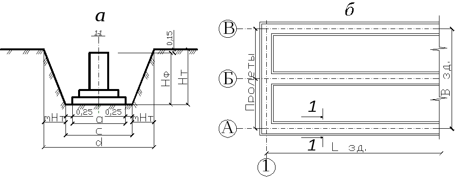 Fig 2.1. Determination of trench volumes
a-section; b-plan.
 (1)
(1)
where: c - the width of the trench along the bottom, is assumed to be 0.5 m more than the length of the lower foundation step a, (c \u003d a + 0.5 m).
H T - trench depth, m (assumed to be 0.15 m more than the height of the foundation), is calculated by the formula:
 (2)
(2)
d- width of the trench along the top, m at the coefficient of slope of the soil m according to Table 2, depending on the given type of soil and the depth of the trench, is determined by formula 3:
 (3)
(3)
L T - trench length, m (accepted depending on the length and number of sections).
2. Pit volume(V k m 3) (Fig. 2.2, 2.3) for a free-standing foundation with a column spacing of 12 m or a solid foundation pit for a building with a rectangular base and constant slopes around the entire perimeter is determined by formula 4:
 (4)
(4)
where: c and e - respectively, the width and length of the pit along the bottom, m.
Excavation plan Section A-A

Rice. 2.2. Pit dimensions.
 Rice. 2.3. Determination of the volume of the pit for a separate foundation.
c and e values for separate foundations taken 1 m more than the corresponding dimensions of the lower step of the foundation: (c=a+1, e=b+1 m).
For a solid pit (Fig. 2.4) c \u003d B zd + a + 1; e \u003d L zd + in + 1
where B zd - the width of the building, m (the distance between the extreme longitudinal axes);
L zd - the length of the building, m (the distance between the extreme transverse axes);
d and f are the width and length of the pit along the top, respectively, m;

Rice. 2.4. Determining the volume of the excavation for the building.
Scheme of the transverse (longitudinal) section of the pit.
m - soil slope coefficient, taken according to Table 2.2, depending on the given type of soil and the depth of the pit.
Table 2.2. Soil slope coefficients m.
|
Slope coefficients m depending on the depth of excavation H in, m up to: |
|||||||
|
Bulk | |||||||
|
Sandy and gravelly | |||||||
|
loams | |||||||
|
Dry loess clays | |||||||
The calculation data are summarized in Table 2.3.
Table 2.3. Sheet of calculation of volumes of excavations.
|
Boiler type or trenches. |
Number of tr. and boiler. |
Coef. slope, m |
Foundation parameters, m |
Parameters of trenches or pits, m |
Soil volume, m 3 |
|||||||||
|
for 1 boiler or tranche. | ||||||||||||||
3. The volume of soil left on the construction site for backfilling the sinuses (  m 3) after the installation of foundations is calculated by formula 5:
 (5)
(5)
Where:  - the total volume of all pits and trenches for the foundations of the building, m 3
 - the total volume of all foundations of the building, m 3 (see table. 2.4).
 - coefficient of residual loosening, taken according to table. 2.4 depending on the type of soil.
Table 2.4. Soil loosening indicators
|
Soil name |
Soil loosening coefficient |
Volumetric mass of soil |
|
|
K p (initial increase in soil volume after development) |
K o.r. - (residual loosening of soils) |
||
|
Loam is light and loesslike | |||
|
Loam medium | |||
|
clay soft | |||
|
Clay hard | |||
After mechanized excavation of the soil, it is necessary to clean the bottom of the pit (trench). The bottom of the trench or free-standing pits is cleaned manually. General excavation - by a bulldozer or excavator-planner to remove the shortage of soil.
The volume of soil when cleaning the pit (trench) is determined by the formula:
V h = F PC × h h ,
Where V h - the volume of soil obtained by cleaning the bottom of the pit (trench) in m 3;
F PC- the area of \u200b\u200bthe sole of the pit (trench), m 2;
h h- cleaning depth.
The depth of cleaning the bottom of the pit (trench) is taken according to table 2.5.
An example of a scheme for the production of work when cutting the soil of a vegetative layer is given in Appendix I, fig. I.1.
Table 2.5. Stripping depth
4. Calculation of the volume of foundations (  m 3) of all grades given in the assignment, as well as the foundations of expansion joints, is determined by external geometric dimensions and is given in tabular form in Table. 2.6.) according to formula 6:
Where:  - length of foundation steps, m;
 - width of foundation steps, m;
 - height of foundation steps, m;
(A P b P h P ) – length, width, height of the sub-column, m.
Table 2.6. Volumes of monolithic reinforced concrete foundations.
5. Volume of excess soil (  m 3) to be removed from the construction site by dump trucks is determined by formula 7:
Where: TO n- coefficient of initial loosening, taken according to Table 3.
All calculations are summarized in Table 2.7 to compile the balance of earth masses.
Table 2.7. Earth mass balance.
|
Name of works |
Conventions |
counting |
The volume of the entire soil, m 3 |
|
|
Excavation soil volume | ||||
|
Excavation soil volume, taking into account the coefficient. initial loosening Kp |
Vvp \u003d Vv * Kpr | |||
|
Volume of foundations |
By geometric dimensions | |||
|
Volume of backfill soil with coefficient residual loosening Core |
Voz \u003d (Vvp-Vf) / Kor | |||
|
The volume of soil to be removed |
Vizl \u003d Vvp-Voz |
INTRODUCTION
The basis of reliable power supply to consumers with electrical energy is the trouble-free operation of cable lines. Uninterrupted power supply to consumers of urban networks and industrial enterprises depends on the new, progressive technological solutions and the use of modern cable fittings, from high-quality cable laying and strict compliance with all requirements for the operation of cable lines.
Despite the growing quality of the insulation of cable lines, damage cannot be ruled out. Moreover, the specific amount of damage is a fairly stable characteristic of a certain class. electrical networks.
Defect location (FLO) is the most complex, and often the longest technological operation to restore a damaged network element. This is an operational task of dispatching services of electrical networks.
The cost of funds for WMD is a significant part of the operating costs in power grids. The share of capital expenditures on WMD devices in total capital expenditures is relatively small. The introduction of progressive methods and means of WMD gives a significant economic effect. It consists of timely detection weaknesses in cable lines, by carrying out preventive high-voltage tests, reducing power supply interruptions, reducing the amount of repair work and reducing the cost of earthworks in the summer. The set of operations to search for damage and restore the cable line is considered as a single interconnected system.
1. MAIN CHARACTERISTICS AND PREVENTION OF CABLE NETWORKS
1.1. Power cable parameters
Power cables are designed to transmit electricity used to power electrical installations. They have one or more insulated cores enclosed in a metal or non-metal sheath, on top of which, depending on the conditions of laying and operation, there may be a protective cover, and, if necessary, armor.
Power cables consist of conductive cores, insulation, sheaths and protective covers. In addition to these basic elements, the design of power cables may include screens, neutral conductors, protective earth conductors and fillers (Fig. 1.1).
Conductive wires intended for passing electric current, are basic and zero. The main conductors are used to perform the main function of the cable - the transmission of electricity. Zero cores, designed for the flow of the current difference of the phases (poles) with their uneven load, are connected to the neutral of the current source.
Protective ground conductors are auxiliary and are designed to connect non-energized metal parts of the electrical installation to which the cable is connected ... with the protective ground loop of the current source.
Insulation serves to ensure the necessary electrical strength of the current-carrying conductors of the cable in relation to each other and to the grounded sheath (ground).
Screens are used to protect external circuits from the influence of electromagnetic fields of currents flowing through the cable, and to ensure symmetry electric field around the cable cores.
Fillers are designed to eliminate free gaps between the structural elements of the cable in order to seal, give the required shape and mechanical stability of the cable structure.
Rice. 1.1. Cross-sections of power cables: A- two-core cables with round and segmented cores ; b- three-core cables with belt insulation and separate sheaths; V- four-core cables with zero residential sector, round and triangular shape; 1
- conductive wire; 2
- zero core;
3-
- core insulation; 4
- screen on a conductive core; 5
- belt isolation;
6
- filler; 7
- screen on core insulation; 8
- shell; 9
- armored cover;
10
- outer protective cover
Sheaths protect the internal elements of the cable from moisture and other external influences.
Protective covers are designed to protect the cable sheath from external influences. Depending on the design of the cable, the protective covers include a pillow, an armor cover and an outer cover.
Letter codes are assigned to different cable designs. The values of the letter indices in the designation of cable brands are given in Table. 1.1.
Power cables with paper insulation, impregnated or lean, designed for use in fixed installations and in the ground at temperatures environment from plus 50 to minus 50 °C and relative humidity up to 98% at temperatures up to plus 35 °C. They are manufactured for rated voltages of 1, 6 and 10 kV AC with a frequency of 50 Hz, but can be used in DC networks (Fig. 1.2).

Rice. 1.2. Power cables: A- from paper; And b- rubber insulation;
1 - outer cover; 2 - armored tape; 3 - cable yarn;
4 - cable paper; 5 - shell; 6 - belt isolation;
7 - filler; 8 - core insulation; 9 - conductive wire
Power cables with paper insulation, impregnated with a non-draining composition, are designed for laying on vertical and inclined sections of routes without limiting the difference in levels and operation at an ambient temperature of plus 50 to minus 50 ° C and a relative humidity of 98% at temperatures up to plus 35 ° C and are manufactured for voltages of 6 and 10 kV alternating current with a frequency of 50 Hz, but can also be used in direct current networks.
Power cables with plastic insulation, in a plastic or aluminum sheath with or without protective covers, are designed for the transmission and distribution of electricity in stationary installations for a rated alternating voltage of 0.66; 1; 3 and 6 kV with a frequency of 50 Hz.
Cables can be operated at ambient temperature from minus 50 to plus 50 °C, relative air humidity of 98% at plus 35 °C, including when laying outdoors with protection from solar radiation.
Table 1.1
Some alphabetic characters in the designation of cable brands

Note. The cable belonging to the control is indicated by the letter "K" before the brand with copper conductors and after the letter "A" - with aluminum.
1.2. Characteristics of cable structures
The main way of sewerage electrical energy at industrial enterprises are cable lines. On large enterprises the number of cable lines can reach up to 25,000 with a total length of up to 2,500 km. To accommodate such a number of cables, special cable structures are required. The simplest and cheapest structure is an earthen trench, but since the number of damages with this method is about 40%, it is used less frequently compared to laying in special structures.
Enterprises rarely give preference to any one method of laying and use mixed laying more often. The buildings used are:
1. Earth trench. The depth of the trench from the planning mark for cables with voltage up to 10 kV should be 0.8 m, at the intersection of streets, squares - 1.1 m (Fig. 1.3).

Fig.1.3. Cable laying in a trench
A shallower trench depth (up to 0.6 m) is allowed when cables are introduced into buildings, structures, as well as at intersections with underground structures, provided that the cables are protected from mechanical damage in sections up to 5 m long. The width of the trench when laying power cables in it is up to 10 kV is taken not less than that indicated in Table. 1.2 and in fig. 1.4. The cables are laid on the backfill, and on top they fall asleep with a layer of fine earth,
does not contain construction debris and slag. The routes are marked with identification marks fixed on the walls of permanent buildings and structures or on columns made of angle steel (pickets). Signs are placed at the corners and turns of the route, at the installation sites of couplings, at the intersections of communication lines (on both sides), at the entrances to buildings. On signs 100 x 100 mm in size, indicate the voltage sign (in red paint), the designation of the cable route, the distance from the structure (in numbers) and the direction to it (arrows), the number of the sign (in black paint). The background of the sign is white.
Table 2.2
Dimensions of trenches for cables up to 10 kV (to Fig. 2.4)
|
trench type |
Dimensions, mm |
Number of laid power cables, pcs. |
||

Fig.1.4. Dimensions of the trench for laying cables 1 ... 10 kV:
IN 1 - size at the bottom of the trench; IN 2 - surface dimension
land; IN 3 - withdrawal zone
Exemplary samples of identification marks are shown in fig. 1.5.
2. Cable channel- this is a closed and buried (partially or completely) impassable structure in the ground or floor, intended for placing cables in it, laying, inspecting and repairing which can only be done with the ceiling removed.

Fig.1.5. Cable signs:
A- trench; b- cable sleeve; V- trench turn
at an angle
The channel is assembled from precast concrete or monolithic blocks. In the premises, the channels are covered with slabs at the floor level, and in the unprotected area, the channel is buried in the ground by 300 mm, at intersections with the road - by 700 mm and railway tracks - 1000 mm (Fig. 1.6).
Channel sizes:
Width - 600 ... 1200 mm, height - 300 ... 900 mm.
This laying method protects well from mechanical damage, but where metal or aggressive substances can be spilled, the construction of cable channels is not allowed (Fig. 1.7).
3. Cable tunnel- this is an underground structure (corridor) with supporting structures located in it for placing cables and couplings on them, allowing for laying, repairs and inspections with free passage along the entire length (Fig. 1.8)
KT is constructed from prefabricated reinforced concrete and covered with waterproofing from the outside. Deepening - 0.5m.
Passages in cable tunnels, as a rule, should be at least 1 m, however, passages can be reduced to 800 mm in sections no longer than 500 mm.

Rice. 1.6. Precast concrete channels: A- tray type LK;
b- from prefabricated slabs of the SK type;
1 - tray; 2 - floor slab; 3 - sand preparation;
4 - plate; 5 - base.
|
|

Fig.1.7. Options for laying cables in cable channels:
A- arrangement of cables on one wall on hangers;
b- the same on the shelves; V- the same on both walls on suspensions;
G- the same on one wall on hangers, on the other on shelves;
d- the same on both walls on the shelves; e- the same at the bottom of the channel
The floor of the tunnel must be made with a slope of at least 1% towards water collectors or storm sewers. In the absence of a drainage device, drainage wells measuring 0.4 x 0.4 x 0.3 m should be installed every 25 m, covered with metal gratings. If it is necessary to move from one mark to another, ramps with a slope of no more than 15 ° should be arranged.
The tunnels must be protected from the ingress of groundwater and process water and ensure the drainage of soil and storm water.
Tunnels should be provided primarily with natural ventilation. The choice of a ventilation system and the calculation of ventilation devices are made on the basis of heat releases specified in construction assignments. The temperature difference between the incoming and outgoing air in the tunnel should not exceed 10 ºС. Ventilation devices should be automatically switched off, and air ducts should be equipped with dampers with remote or manual control to stop air from entering the tunnel in the event of a fire.
The tunnel must be provided with fixed means for remote and automatic fire extinguishing. The source of fire may be cables, cable connectors. A fire can be caused by careless handling of fire and flammable materials during installation or repair work. The choice of fire extinguishing agents is made by a specialized organization.
In tunnels, sensors should be installed that react to the appearance of smoke and an increase in ambient temperature above 50 °C. Collectors and tunnels must be equipped with electric lighting and a power supply network for portable lamps and tools.
Long cable tunnels are divided along the length by fire-resistant partitions into compartments no more than 150 m long with doors at least 0.8 m wide in them. Doors from the extreme compartments must open into the room or out. The door to the room must be opened with a key from both sides. The outer door must be equipped with a self-closing lock that can be opened with a key from the outside. Doors in the middle compartments should open towards the stairs and be equipped with devices that fix their closed position. These doors open from both sides without a key.
The laying of cables in collectors and tunnels is calculated taking into account the possibility of additional laying of cables in the amount of at least 15%.
Power cables with voltages up to 1 kV should be laid under cables with voltages above 1 kV and separated by a horizontal partition. Various groups cables, namely working and backup voltages above 1 kV, are recommended to be laid on different shelves with their separation by horizontal fireproof partitions. As partitions, asbestos-cement slabs are recommended, pressed unpainted with a thickness of at least 8 mm. The laying of armored cables of all sections and unarmored conductors with a cross section of 25 mm 2 and above should be carried out along structures (shelves), and unarmored cables with a conductor cross section of 16 mm 2 or less - on trays laid on cable structures.
Cables laid in tunnels must be rigidly fixed at the end points, on both sides of the bends and at the splices.
To avoid the installation of additional couplings, the construction length of the cables should be selected.
Each coupling on power cables must be laid on a separate shelf of supporting structures and encased in a protective fire casing, which must be separated from the upper and lower cables along the entire width of the shelves by protective asbestos-cement partitions. In each tunnel and channel, it is necessary to provide free rows of shelves for laying couplings.
For the passage of cables through partitions, walls and floors, branch pipes made of fireproof pipes must be installed.
In places where cables pass in pipes, the gaps in them must be carefully sealed with non-combustible material. The filling material must provide adhesion and be easily broken in case of laying additional cables or their partial replacement.
Unarmored cables with a plastic sheath can be fastened with brackets (clamps) without gaskets.
The metal armor of cables laid in tunnels must have an anti-corrosion coating. The distance between the shelves of cable structures when laying power cables with voltage up to 10 kV must be at least 200 mm. The distance between the shelves when installing a fire-resistant partition when laying cables must be at least 200 mm, and when laying the coupling 250 or 300 mm - depending on the size of the coupling (Fig. 1.8).

Fig.1.8. Location of cables in the tunnel: A- rectangular tunnel
sections; b- circular tunnel;
1 - tunnel block; 2 - rack ; 3 - shelf; 4 - lamp;
5 - zone of fire detectors and pipelines of mechanized cleaning
dust and fire fighting; 6 - power cables; 7 - control cables
4. Cable collector- this is a structure designed for the general placement of cable lines, heat pipes and water pipes.
The collector is built from reinforced concrete structures round and rectangular sections. Circular collectors are made at a depth of not more than 5 m in a closed way. The collector is equipped with ventilation, pumps and is controlled from the control room. A telephone connection must be provided. Collector dimensions: diameter - 3.6 m; width - 2.5 m; height - 3.0 m
(Fig. 1.9).
5. Cable block- this is a structure with pipes (channels) for laying cables with wells related to it.
Cable blocks are constructed from reinforced concrete panels 6 m long with 2-3 channels inside from asbestos-cement or ceramic pipes. The blocks are laid on a pad of reinforced concrete and protected with waterproofing. Depth of laying - not less than 0.7 m,
and at intersections - at least 1 m. The joints of the panels are poured with a solution, having previously laid a bundle of tow in the gap. Every 150 m, walk-through or branching wells are installed. The minimum height of wells is 1.8m. Laying in blocks is the most reliable, but less economical.
|
|
|
|


Fig.1.9. Arrangement of cables in round and rectangular collectors
sections: 1 - cables; 2 - water pipes; 3 - heating pipes
Laying cables in blocks is recommended: in the following cases: at intersections with railways and highways; with a large number of other underground communications and structures; the probability of spilling metal or aggressive liquids in the places where cable routes pass; laying cable lines in soils that are aggressive with respect to the cable sheath; the need to protect cables from stray currents.
For the construction of blocks, two- and three-channel reinforced concrete panels are used (Fig. 1.10), designed for laying in dry, wet and water-saturated soils, asbestos-cement pipes to protect cables from stray currents, ceramic pipes to protect cables in aggressive and water-saturated soils (with necessary - and in dry soils). When choosing materials for cable blocks, one should take into account the level of groundwater and their aggressiveness, as well as the presence of stray currents.

Fig.1.10. Scheme of pulling the cable in the cable block:
1 - drum with cable; 2 - corner roller; 3 - cable; 4 - detachable funnel;
5 - rope; 6 - rope roller; 7 - installation for tension control
In places where the direction of the route changes or the depth of the blocks, as well as on straight sections of great length, cable wells are made. The number of wells on the straight sections of the block should be minimal, while the distance between adjacent wells should be taken as much as possible, taking into account the building lengths of the cables, the allowable pulling forces and the laying conditions.
The dimensions of the cable wells must provide normal (conditions for pulling cables with a maximum cross section
(3 x 240) mm2 with cable bending radius R = 25 d, replacing them if necessary, installing couplings with protective metal casings 1250 mm long.
Cable wells are made of brick or precast concrete and are of the following types: direct type through passage, angular - for changing the direction of block sewerage with rotation angles of 90, 120, 135 and 150 °, tee straight and with a rotation angle of 120 and 150 °, cruciform.
The slope of the well floor should be 0.003 towards the water collector. The grate of the water collector must be metal. Installation of embedded parts for cable structures is carried out during the installation of wells.
Mouths (manholes) of cable wells should be round or oval and closed with double metal covers. On the bottom cover, it is necessary to provide a device for removing the hatch. Round hatches are designed only for one-sided pulling of cables, their diameter must be at least 700 mm, oval hatches are designed for double-sided pulling of long cables with a cross section of up to
185 mm 3. Width of the oval hatch - 800, length - 1800 mm. Cables with a cross section of 240 mm 2 and above should be pulled without a loop, in one direction. Wells should be provided with steel brackets or a metal ladder for descent. Due to the fact that cable wells are an expensive part of block sewerage, it is recommended to use cable chambers when switching from block sewerage to trench sewage. When making blocks from asbestos-cement pipes, the inner surfaces of the pipes and their joints must be lubricated with BN-IV bitumen diluted in kerosene (2 mass parts of bitumen and 1 mass part of kerosene). In dry soils, all outer surfaces of pipes and their joints must be protected with paint waterproofing in two layers, and in wet and water-saturated soils, with glued waterproofing in two layers.
For blocks made of ceramic pipes, in aggressive soil, the voids between the pipes must be filled with concrete, in non-aggressive soil, concrete is needed only at the pipe junctions, and the rest must be covered with sand or sifted soil.
The depth of cable blocks (counting from the top cable) should be at least 1 m at the intersection of streets and squares and 0.7 m in all other cases. In industrial premises and in closed areas, the depth is not standardized.
The route of cable blocks is straight. When crossing engineering structures, the route approaches perpendicular to their axis. Deviation from the right angle is allowed, but not more than 45 °, if this is dictated by the location of the place where the blocks are entered into the building or the presence of structures built on the highway.
Each cable block must have 10% redundant channels, but not less than one channel.
6. Cable rack- it is above ground or ground open horizontal or inclined extended cable construction. Distinguish between through and impassable flyovers. They are made from reinforced concrete or rolled steel. The distance between the supports is 12 m. Stair entrances should be arranged on the through passages, the distance between them is about 150 m. Mounting openings are constructed in the floor of the overpasses. With a small number of cables, they are laid along technological racks. This method of laying, despite the high cost, is convenient and is increasingly used.
7. Cable gallery- this is a fully or partially closed flyover.
Laying cables with voltage up to 10 kV with a cross section up to
240 mm 2 on overpasses and in galleries is used for laying inter-shop electrical networks across the territories of industrial enterprises. Special cable racks must be equipped for laying cables across the territories of chemical and petrochemical enterprises, where the possibility of pouring substances that destroy the cable sheaths is not ruled out. It is allowed to use technological racks for combined laying of pipelines and cables. Cable overpasses are made of impassable reinforced concrete and metal, reinforced concrete, metal and combined. Impassable overpasses are made in such a way that it is possible to service them from specially equipped machines.
On fig. 1.11 shows galleries, cable racks with and without sun visors, of various designs from unified elements. With the combined laying of pipelines and cables, the overpasses are performed individually. For cable overpasses, the main distances between the supports are 6 and 12 m. On certain sections of the route, if necessary, the distance between the supports can be 9 m. The main height of the construction of overpasses from the roadbed is 5 m. 2.5 m (from the planning level of the ground) with transitions at the intersections with roads to a height of:
5 m - at the intersection with roads;
6 m - when crossing with non-electrified railways (from the rail head);
7.1 m - when crossing with electrified railways (from the rail head).
The angles of turns of overpasses, branches, transitions from one mark to another, junctions with buildings, vertical shafts and stairs are carried out individually in each case, depending on local conditions.
Impassable overpasses without sun-protected visors are used for laying 16, 24 and 40 cables with spans between supports of 6 m, and for laying 24 and 40 cables - 12 m; walk-through one- and two-section flyovers - for laying 64 and 128 cables with spans of 6 and 12 m.
The vertical distance between the shelves on impassable overpasses is 200 mm, on walk-throughs - 250 mm. The horizontal distance between the shelves is 1 m, but it can be increased when developing a specific project, taking into account the load-bearing capacity of cable structures. When laying cables in an aluminum sheath with a cross section of 50 mm 2 or more, the distance between cable structures is allowed up to 6 m. The sag of cables between structures should be 0.4 m.
For laying on overpasses, cables without an outer combustible cover, having anti-corrosion protection, or with an outer protective cover made of non-combustible materials, should be used.
The location of cables on the shelves, the distances between the cables, the installation of couplings and other conditions are the same as when laying cables in tunnels (Fig. 1.12).
|
|
|
|

Rice. 1.11. Laying cables on cable racks and galleries with and without sun visors (beginning):
A- impassable overpass; b- overpass; V- one-sided gallery; G- double-sided gallery; d- three-wall combined gallery; e- impassable overpass without sun visors; and- overpass without sun visors; 1
- reinforced concrete base; 2
- reinforced concrete column; 3
- metal column; 4
- Sunshield;
5
- reinforced concrete beam; 6
- cable construction; 7
- cables; 8
- solar panels; 9
- removable sun panels; 10
- steel profile; 11
- main load-bearing metal trusses; 12
- metal flooring; 13
- metal traverse; 14
- reinforced concrete traverse; 15
- main load-bearing reinforced concrete beams
|
|

Rice. 1.11. Laying cables on cable racks and galleries
with and without sun visors (continued):
16 - fireproof partition; 17 - rack; 18 - plate; 19 - coupling; 20 - control cables; 21 - bundle of cables with cross section up to 16 mm 2

Fig.1.12. General form tunnel type flyovers:
1 - drum with cable; 2 - cable; 3 - corner roller; 4 - linear roller;
5 - rope; 6 - winch.
Depending on the type of structure, the following number of cables can be laid: earth trench - 6, cable block - 20, cable channel and overpass - 24, cable gallery - 56 and cable tunnel - 72.
1.3. Preventive measures to increase
reliability of cable lines
To ensure the correct operation of each cable line (CL), the following is required:
1) as-built drawings for cable lines and other cable structures;
2) passports of cable lines and structures;
3) address lists of cable structures.
The executive drawing is made to scale and the CL is tied to permanent fundamental landmarks. Lines of different voltages have their own designations.
The CL passport is compiled on the basis of acceptance documentation and contains the following information:
1) brand of cable and its length;
2) scheme of the route with reference marks;
3) data on couplings and terminations;
4) information on protection against corrosion, vibration and mechanical damage;
5) information about preventive tests with increased voltage;
6) information about damage and repair of cable lines;
7) information about the load of CL.
All this information must be in the data bank. A correctly drawn up passport can allow you to accurately assess the condition of the CL and make a timely decision on overhaul lines.
A single dispatch number is set for each CL. If the line consists of several parallel lines, then a letter is added to the number (A, B, C, etc.). The address list indicates the name of the structure (RP, TP, tunnel, well), its dispatch number and the address of the nearest city building.
Every year, as part of the compilation of a list of scheduled preventive repairs, a nomenclature of work is developed, which includes:
1) terms of performance of works;
2) preventive inspections of cable lines;
3) measurement of current loads during periods of maximum and minimum power consumption;
4) preventive tests with increased voltage;
5) control over cable heating and stray currents;
6) CL repair.
The operational supervision of the cable is carried out in accordance with the rules of technical operation and local instructions. For persons and organizations guilty of damage to the cable, penalties have been established. The frequency of preventive examinations is established in accordance with. During floods and autumn rains, extraordinary inspections of cable lines are carried out. At the intersections of cable lines with ditches and ravines, the presence of erosion and landslides that threaten the integrity of the cable lines is checked. When examining the CL, check:
1) carrying out uncoordinated work on the track;
2) the presence of benchmarks;
3) the condition of the pipes when entering the building or exiting the cable to the overhead line support.
4) the absence of combustible gases and flammable materials in cable structures;
5) work of lighting, ventilation;
6) air temperature in cable structures;
7) the state of anti-corrosion coatings and building parts (hatches, doors).
The results of the inspections of cable lines are recorded in the log of defects and malfunctions and transferred to the personnel who directly operate these lines. The operating personnel provides access to work on the cable lines and supervises the correct conduct of work in the specified area.
Control over the state of cables during operation is provided by measuring the temperature of lead, aluminum sheaths or armor. The temperature is measured with a thermocouple. For this purpose, a pit measuring 900 x 900 mm is prepared and the thermocouple wire is soldered to the cable sheath. Wires are led out through the pipe and the pit is filled up. The temperature is measured simultaneously with the measurement of CL loads every 2-3 hours during the day. In structures with open cable laying, the temperature is measured with an ordinary laboratory thermometer, fixing it on the cable sheath.
Load measurements are made in December and May. Registration of power consumption parameters can be performed by self-recording wattmeters and ammeters, electric energy meters, as well as by panel devices, the readings of which are recorded in the statement. The measurement results serve as the basis for carrying out measures on the cable lines that ensure their trouble-free operation. One of these measures is preventive testing of cable lines with increased voltage. To prevent the breakdown of a weakened place of cable lines, they are routinely tested with increased DC voltage. Lines 6 ... 10 kV are tested with five times the rated voltage for 5 minutes for each phase at least once every 3 years. During the test, attention is paid to the nature of the change in the leakage current. The cable is considered to have passed the test if there was no breakdown and shocks of the leakage current or its increase after the current has reached a steady value. Before and after the test, the insulation resistance is measured with a 2.5 kV megger, which is not standardized, but must be at least a few mΩ. The tests are carried out using a mobile unit of the AII-70 type. After testing, the cable must be discharged through the discharge resistance of the installation.